Lens focal length measuring device and method based on Fizeau interferomenter

A technology of Fizeau interferometer and lens focal length, which is applied in the field of optical measurement and can solve the problems of low precision, inconvenient operation, and inability to perform measurement.

Inactive Publication Date: 2014-11-26
NANJING UNIV OF SCI & TECH
View PDF6 Cites 12 Cited by
  • Summary
  • Abstract
  • Description
  • Claims
  • Application Information

AI Technical Summary

Problems solved by technology

Among them, the magnification method and the precision angle measurement method require the focal length of the collimator lens to be more than 3-5 times the focal length of the measured lens when measuring the telephoto lens. Generally, the focal length of the telephoto lens is greater than 1m, that is, the collimator needs to be designed in More than 3-5m, and limited by the length of the optical bench, the operation is inconvenient, and it is more suitable for measuring the focal length of short-focus lenses; the spectrum analysis method has high test accuracy, but requires expensive input equipment and output measurement equipment on the spectrum plane, under ordinary experimental conditions It cannot be measured, and it is more suitable for measuring short and medium distance focal lengths
The Taber-Mohr method utilizes Taber "self-imaging" and the magnification characteristics of the Moire fringe pattern for telephoto measurement, but the accuracy is low. The accuracy of this method is between 2% and 4%, which cannot meet the focal length accuracy requirements high system

Method used


Image

  • Lens focal length measuring device and method based on Fizeau interferomenter
  • Lens focal length measuring device and method based on Fizeau interferomenter
  • Lens focal length measuring device and method based on Fizeau interferomenter

Examples


Embodiment

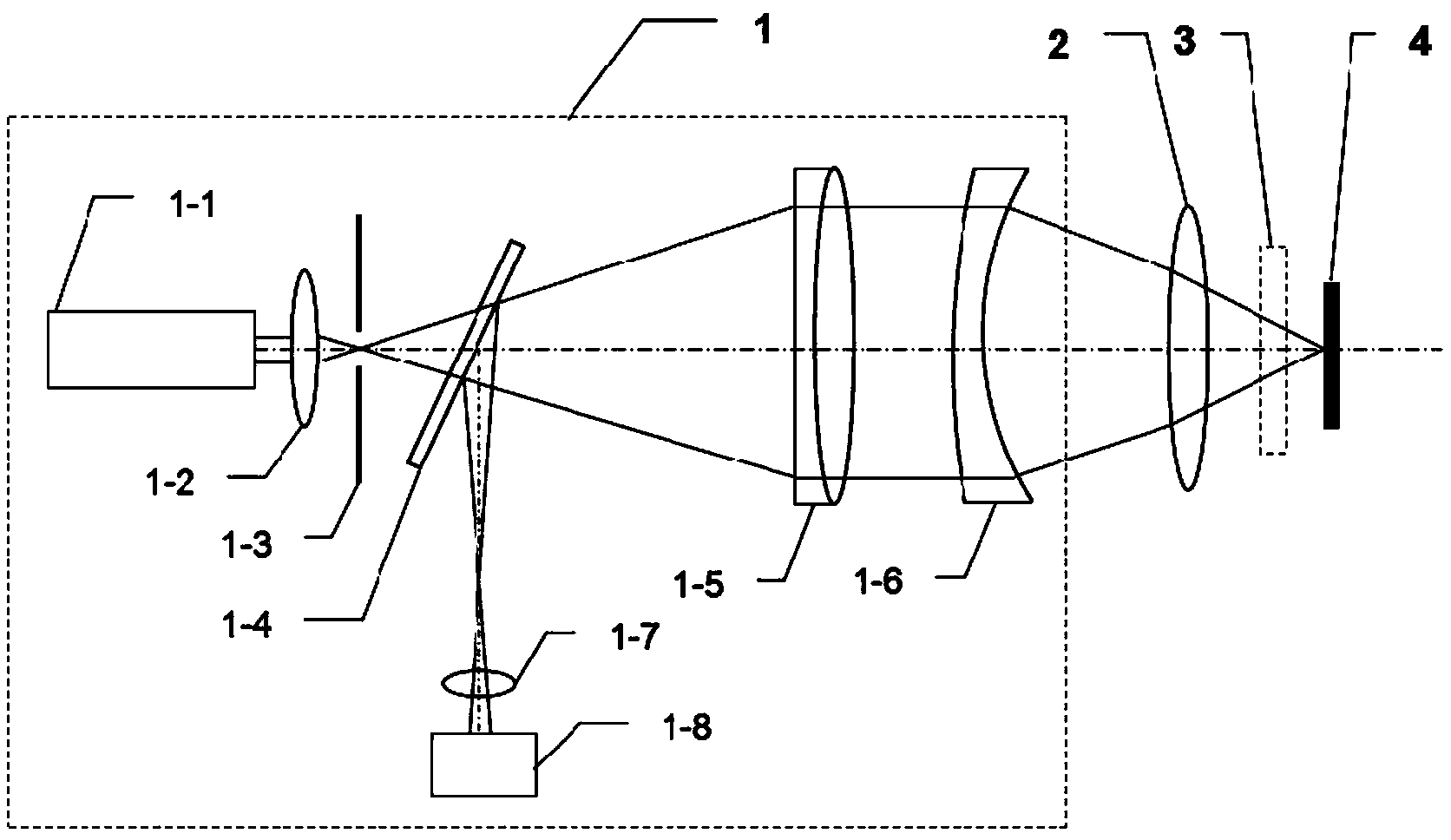
[0093] In the embodiment, the focal lengths of two positive lenses and one negative lens are sequentially detected by using the method of the present invention, and the initial values ​​of the focal lengths of these three lenses are f=536.3mm, 377.9mm, -254.6mm. The working wavelength of the polarization-stabilized He-Ne laser 1-1 is λ=632.8nm, the light beam is converged by the microscope objective lens 1-2, and the focal point is projected onto the spatial filter 1-3, and then collimated by the collimating objective lens 1-5, A beam of parallel light is obtained and enters the interference optical path.

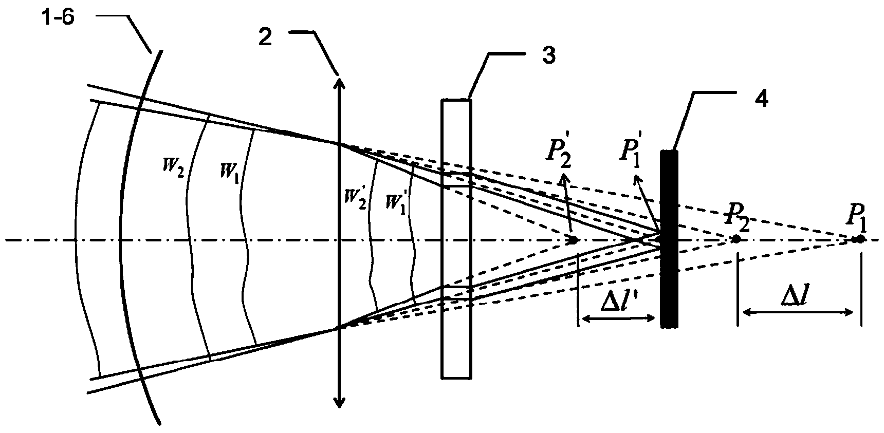
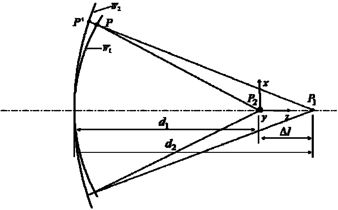
[0094] The steps of using the Fizeau interferometer to detect the focal length of two positive lenses and a negative lens are as follows: Figure 4 As shown, the specific detection steps are:

[0095] 1) Measure the thicknesses of two parallel plates using a white light interferometer (Wyko NT9100) with a resolution of 0.1 μm. The material of the two parallel plates is nBk...


PUM


Abstract

The invention discloses a lens focal length measuring device and method based on a Fizeau interferomenter. According to the lens focal length measuring method, two parallel flat plates different in thickness are sequentially inserted into an interference cavity in the lens focal length measuring device for introducing axial displacement of an object point and a image point, and the lens focal length is measured. The lens focal length measuring method includes the steps that a glass flat plate is placed at the cat eye position, and when no parallel flat plate is placed in a test light path, the difference W1-W0 of test wavefront data W1 and reference wavefront data W0 is obtained through phase shift interferometry; the two parallel flat plates different in thickness are respectively arranged in the test light path, and the wave difference W2-W0 and the wave surface W3-W0 which are different from each other are obtained through phase shift interferometry; the wave difference W2-W1, the wave difference W3-W1 and a Gaussian imaging formula are obtained through calculation by adopting a wavefront difference algorithm, and a calculation formula of the lens focal length is derived. Damage to the surface of a lens is avoided by the adoption of the non-contact measuring method, and the lens focal length measuring device and method are suitable for measuring positive and negative lens focal lengths.

Description

technical field [0001] The invention belongs to the technical field of optical measurement, in particular to a lens focal length measurement device and method based on a Fizeau interferometer. Background technique [0002] The focal length is a very important parameter to characterize the optical system. The simplest and most direct method for measuring the focal length of a lens is to irradiate the measured lens with parallel light, and then measure the distance from the measured lens to the focal point to obtain the focal length of the lens; but the position of the focal point is different from the The collimation of the irradiated parallel light is directly related, and the position of the focal point is difficult to determine precisely, especially when the focal length of the lens is very long. [0003] Traditional focal length measurement methods include magnification method, precision angle measurement method, spectrum analysis method and Taber-Moore method, etc. Amon...

Claims


Application Information

Patent Timeline
Patent Type & Authority Applications(China)
IPC IPC(8): G01M11/02
Inventor 高志山杨忠明田雪王凯亮王新星窦健泰袁群
Owner NANJING UNIV OF SCI & TECH
Why Eureka
Try Eureka