Plug-in piece type adjustable laser attenuation device

A laser attenuation and insert type technology, which is applied in the direction of optics, optical components, instruments, etc., can solve the problems of easy damage, and achieve the effect of good uniformity, small deformation, and high adjustment accuracy of attenuation

Active Publication Date: 2014-11-26
SHANGHAI INST OF OPTICS & FINE MECHANICS CHINESE ACAD OF SCI
View PDF4 Cites 2 Cited by
  • Summary
  • Abstract
  • Description
  • Claims
  • Application Information

AI Technical Summary

Problems solved by technology

[0004] The invention proposes a plug-in adjustable laser attenuation device, which overcomes the practical problems that the existing light intensity attenuation device is easy to be damaged and changes the quality of the spot affecting subsequent use, improves the ability to resist laser damage, reduces the impact on beam quality, and expands Attenuators for the Attenuated Laser Wavelength Range

Method used


Image

  • Plug-in piece type adjustable laser attenuation device
  • Plug-in piece type adjustable laser attenuation device
  • Plug-in piece type adjustable laser attenuation device

Examples


Embodiment 1

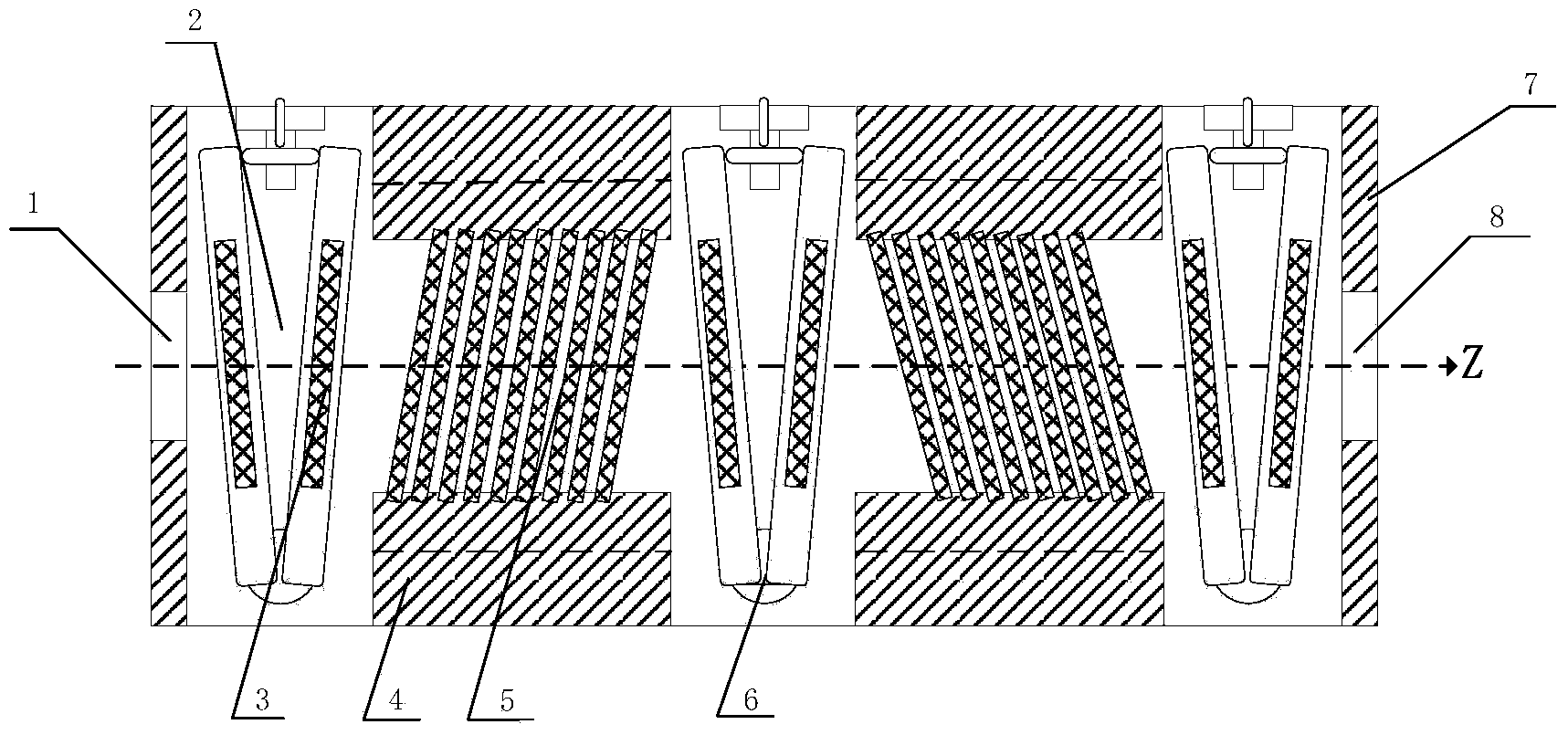
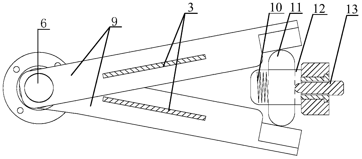
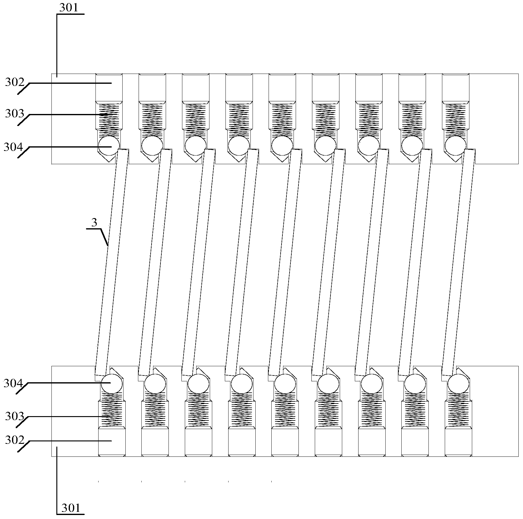
[0027] Embodiment 1: Turn on the laser, the laser beam passes through the incident light-passing hole 1, and a power meter 9 is placed near the exit light-passing hole 8 to observe the attenuated laser beam energy in real time. According to the desired attenuation value, firstly increase or decrease the attenuation lens 3 to realize the rough adjustment of the beam pass rate, and then adjust the fine screw pair 13 to change any fine adjustment attenuation frame pair of the two lens holders with the attenuation lens inserted 9 The angle formed with the straight line passing through the axis of rotation and perpendicular to the Z axis may be 4.5°. The laser beam is repeatedly attenuated by the attenuating lens 3 to obtain a predetermined attenuation value and then output through the exit light hole 8.

Embodiment 2

[0028] Embodiment 2: Turn on the laser, the laser beam passes through the incident light-passing hole 1, and a power meter 9 is placed near the exit light-passing hole 8 to observe the attenuated laser beam energy in real time. According to the desired attenuation value, firstly increase or decrease the attenuation lens 3 to realize the rough adjustment of the beam pass rate, and then adjust the fine screw pair 13 to change any fine adjustment attenuation frame pair of the two lens holders with the attenuation lens inserted 9 The angle formed by the straight line passing through the axis of rotation and perpendicular to the Z axis may be 6.5°. The laser beam is repeatedly attenuated by the attenuating lens 3 to obtain a predetermined attenuation value and then output through the exit light hole 8.


PUM


Abstract

The invention discloses a plug-in piece type adjustable laser attenuation device which comprises a first light through hole, a first fine-tuning attenuation mirror bracket pair, a first fixed attenuation mirror bracket, a second fine-tuning attenuation mirror bracket pair, a second fixed attenuation mirror bracket, a third fine-tuning attenuation mirror bracket pair and a second light through hole. The first light through hole, the first fine-tuning attenuation mirror bracket pair, the first fixed attenuation mirror bracket, the second fine-tuning attenuation mirror bracket pair, the second fixed attenuation mirror bracket, the third fine-tuning attenuation mirror bracket pair and the second light through hole are sequentially fixed to the base and share an optical axis. The first light through hole and the second light through hole are located in the two ends of the base. The first light through hole, the second light through hole, rotating shafts of the fine-tuning attenuation mirror bracket pairs, mirror bases of the fixed attenuation mirror brackets and the base are integrally formed. The plug-in piece type adjustable laser attenuation device is symmetrically distributed about a plane mirror face, wherein the plane mirror face passes through the rotating shaft in the second fine-tuning attenuation mirror bracket pair and is perpendicular to the Z axis. A plurality of attenuation lens can be inserted into the first fine-tuning attenuation mirror bracket pair, the second fine-tuning attenuation mirror bracket pair, the third fine-tuning attenuation mirror bracket pair, the first fixed attenuation mirror bracket and the second fixed attenuation mirror bracket and are made of optical glass.

Description

Technical field [0001] The invention relates to a laser light intensity attenuation device, in particular to a plug-in adjustable laser attenuation device. Background technique [0002] The optical attenuator is a device inserted into the optical path, its purpose is to artificially controllable attenuation of the light intensity, so that the output light can meet the requirements of use in terms of intensity or power. [0003] Current optical attenuators can be divided into two types: absorption type and beam splitting type according to their working principles. The absorption attenuator relies on the absorption of the light beam by the attenuation device itself to attenuate the beam energy or power of the light beam passing through the attenuator. Due to the absorption of beam energy, it is easy to cause the temperature rise of the device itself and introduce some changes in the properties of thermal objects, which will affect the quality of the transmitted beam to a certain ext...

Claims


Application Information

Patent Timeline
Patent Type & Authority Applications(China)
IPC IPC(8): G02B26/02
Inventor 李大伟符燕燕赵元安柯立功郭猛张雷
Owner SHANGHAI INST OF OPTICS & FINE MECHANICS CHINESE ACAD OF SCI
Why Eureka
Try Eureka