Video compression method and system

A video compression and video signal technology, applied in digital video signal modification, electrical components, image communication, etc., can solve the problems of difficult pixel-level video real-time transmission, poor image effect, complex compression algorithm, etc., to simplify complexity, data The effect of reducing the volume, reducing the amount of data and the complexity of calculation

Inactive Publication Date: 2014-11-26
DALIAN NATIONALITIES UNIVERSITY
View PDF4 Cites 26 Cited by
  • Summary
  • Abstract
  • Description
  • Claims
  • Application Information

AI Technical Summary

Problems solved by technology

[0009] For this reason, the purpose of the present invention is to solve problems such as the compression technology existing in the prior art is difficult to solve the network real-time transmission of pixel-level video, the compressed image effect is poor, the compression algorithm is complicated, etc. Video compression method and system for video signal

Method used


Image

  • Video compression method and system
  • Video compression method and system
  • Video compression method and system

Examples


Embodiment 1

[0059] This embodiment provides a video compression processing method suitable for real-time sharing of Wi-Fi wireless networks, focusing on low-complexity real-time video signal compression, and the signal source of the video signal can be a small terminal device such as a smart phone or a tablet computer. video signal. In the transmission and processing of pixel-level video signals, the biggest problem is how to solve the problem of "moving" pixel-level high-definition video information of 2.8Gbps per second or higher resolution pixel-level video information above 2.8Gbps from one end of the network to the other. one end of the problem. For the current commonly used network bandwidth, a general-purpose 150M wireless network is not up to the job.

[0060] The purpose of the video compression method in this embodiment is to compress the obtained high-definition video signals so that they can adapt to the current Wi-Fi wireless network conditions after compression, such as the...

Embodiment 2

[0068] A video compression system implementing the above video compression method is provided in this embodiment, including:

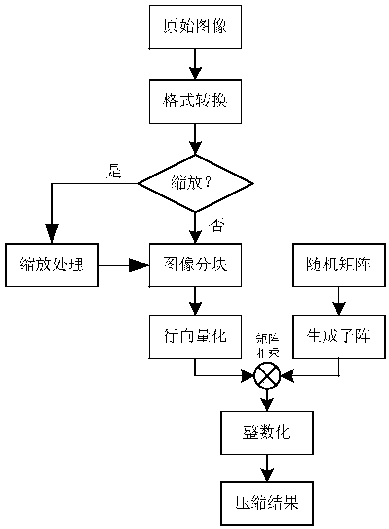
[0069]Format conversion module: obtain the format of the original video signal, and convert the original video signal of the non-YUV format into a video signal of the YUV format; Image block module: process the YUV video signal into blocks respectively to obtain image sub-blocks, wherein The size of the rows and columns of the sub-blocks of the U and V component images is half of the size of the rows and columns of the sub-blocks of the Y component image.

[0070] Row vectorization module: change the form of the image sub-blocks from the image sub-block matrix form to the row vector form according to the row scanning order, and the current line and the next line end-to-end, to obtain the row vector image sub-blocks.

[0071] Scaling judging module: judge whether the data volume of the video signal in the YUV format is greater than a preset threshold, i...

Embodiment 3

[0077] In this embodiment, a specific scaling example is provided. For a video signal with a resolution of 320x24060Hz, the amount of data I required for real-time transmission is 320x240x60x24bit / s or 110592000bit / s, although it can be realized under the current IEEE802.11n wireless network conditions The requirement for real-time transmission of a single video image signal, but a challenge for the parallel transmission of multiple video image signals.

[0078] The specific implementation steps of the video scaling method in this embodiment are as follows:

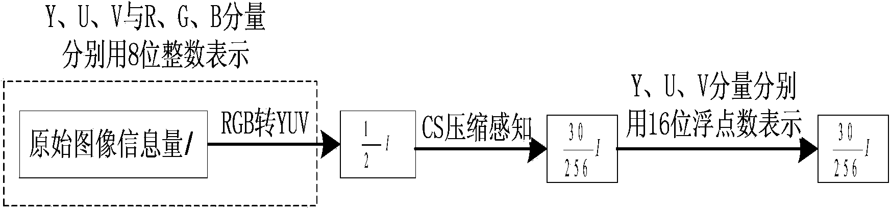
[0079] Step 1: Convert RGB format to YUV format. After format conversion, the amount of information I of the original video data is reduced to The video information is reduced to half of the original. In order to reduce the data volume and calculation complexity of image processing, the RGB format video signal is converted into YUV420 format before compression. Every 4 Y share a set of UV components. When compressing...


PUM


Abstract

The invention provides a video compression method, comprising steps of converting original video signals to YUV format video signals, blocking the components of the original video signals, generating a compression sensing observation matrix, all components of which conform to normal distribution, and utilizing different subsets of the compression sensing observation matrix to compress the all image blocks to obtain the compressed image. The method solves problem that the compression algorithm is complicated and is not suitable for the network real-time transmission technology of the pixel level videos while the processing efficiency and the minimum of the compressed data are guaranteed. The video compression method can get a good compression effect of the data vide, and the pixel level high resolution video after compression is applicable to the low speed Internet.

Description

technical field [0001] The invention relates to the technical field of video data processing, in particular to a video compression method and system suitable for wireless network real-time transmission. Background technique [0002] With the rapid development of digital multimedia terminals, the small screen display of smart phones, tablet computers and other small devices can no longer meet people's daily and work needs. It has become a trend for large-screen terminals (such as large-screen LCD TVs, projectors, etc.) to share video images of small terminals such as mobile phones and tablet computers in real time. However, in the process of real-time transmission and processing of pixel-level high-definition or higher-resolution video signals, the biggest problem is how to solve pixel-level high-definition video information at 2.8Gbps per second or higher-resolution pixel-level video information above 2.8Gbps The problem of "moving" from one end of the network to the other....

Claims


Application Information

Patent Timeline
Patent Type & Authority Applications(China)
IPC IPC(8): H04N19/40H04N19/119H04N19/186H04N19/85
Inventor 杨大伟张汝波刘冠群毛琳吴俊伟
Owner DALIAN NATIONALITIES UNIVERSITY
Why Eureka
Try Eureka