Light emitting device and projection device

A technology for light-emitting devices and projection devices, which can be applied to projection devices, light-emitting materials, lighting devices, etc., can solve the problem of inability to emit blue fluorescence, and achieve the effects of high conversion efficiency and small changes in color reproducibility.

Active Publication Date: 2014-11-26
PANASONIC INTELLECTUAL PROPERTY MANAGEMENT CO LTD
View PDF11 Cites 11 Cited by
  • Summary
  • Abstract
  • Description
  • Claims
  • Application Information

AI Technical Summary

Problems solved by technology

[0027] However, as mentioned above, Ce-activated phosphors such as YAG phosphors cannot emit blue fluorescence. Ther

Method used


Image

  • Light emitting device and projection device
  • Light emitting device and projection device
  • Light emitting device and projection device

Examples


Embodiment approach 1

[0086] Hereinafter, regarding the light-emitting device and the projection device according to Embodiment 1, use Figure 1 to Figure 7 Be explained.

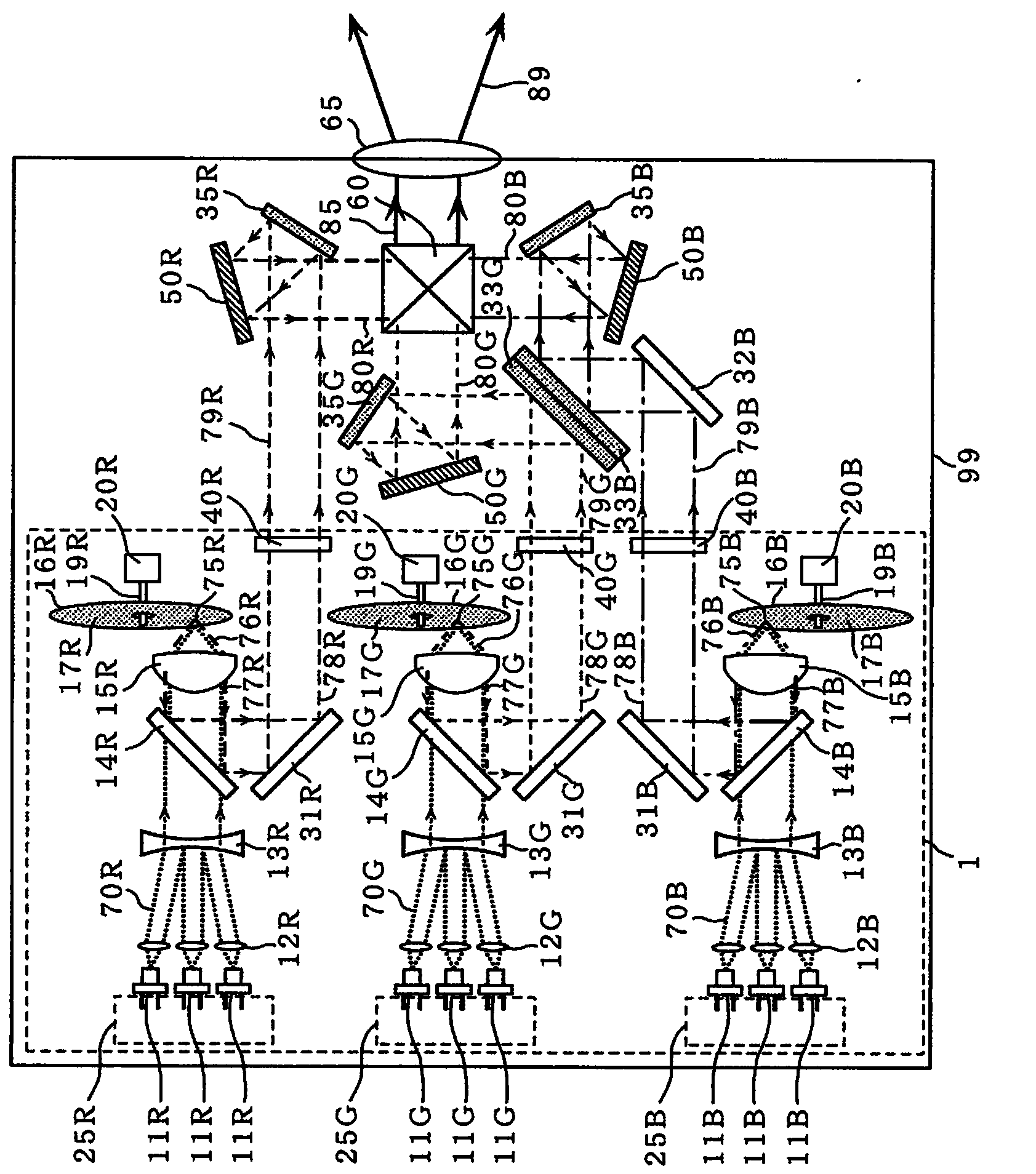
[0087] figure 1 It is a diagram showing the configuration of the light emitting device and the projection device according to the first embodiment.

[0088] like figure 1 As shown, the projection device 99 of this embodiment is mainly composed of the light emitting device 1 , the image display elements 50B, 50G, and 50R, the dichroic prism 60 , and the projection lens 65 .

[0089] The light-emitting device 1 emits light of the following three primary colors, namely, wavelength-converted light 79R of so-called red light whose main emission wavelength is in the range of 580 to 660 nm, wavelength-converted light 79G of so-called green light whose main emission wavelength is in the range of 500 to 580 nm, and main light emission The wavelength-converted light 79B of so-called blue light having a wavelength in the range of 430 ...

Embodiment approach 2

[0151] Next, refer to Figure 8 , Figure 9 as well as Figure 10 , the light-emitting device of Embodiment 2 will be described. In this embodiment, Eu-activated BaMgAl is used as the blue phosphor 10 o 17 . Also, in this embodiment, it will be described that in Eu-activated BaMgAl 10 o 17 In the phosphor, it is also possible to make the efficiency variation coefficient ηB of the energy conversion efficiency 2 / ηB 1 reduced form. In addition, the structure of the light-emitting device of this embodiment is the same as that of the light-emitting device 1 of Embodiment 1, so redundant description is omitted.

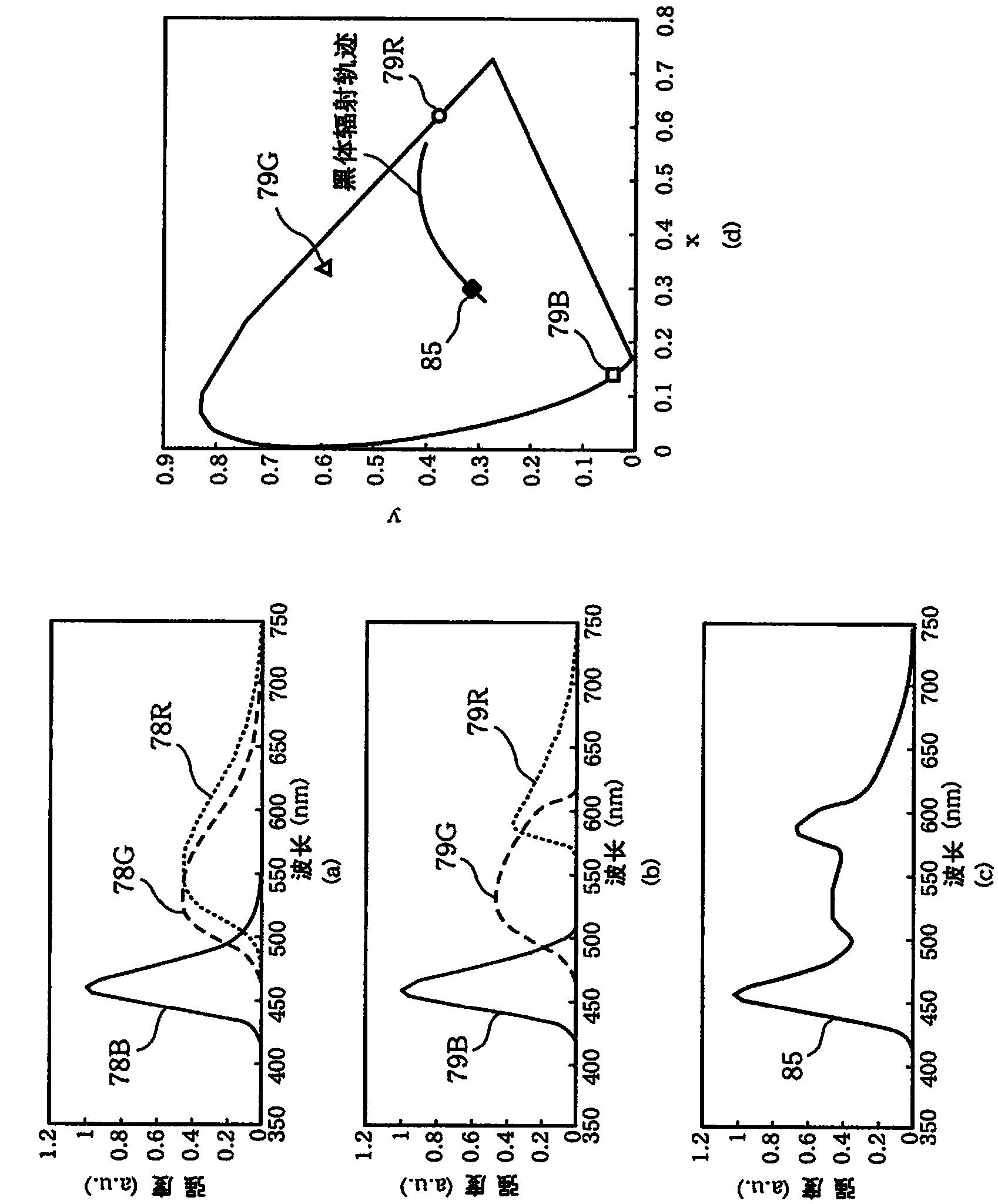
[0152] In the present embodiment, Eu-activated BaMgAl is used as phosphors constituting the wavelength conversion parts 16B, 16G, and 16R, respectively. 10 o 17 , Ce-activated Y 3 (Al, Ga) 5 o 12 , Ce-activated Y 3 Al 5 o 12 . Figure 8 The spectrum of the wavelength-converted light 78B of this embodiment and the spectrum of the combined light 85 of the w...

Embodiment approach 3

[0162] Next, according to Figure 11 as well as Figure 12 , the light emitting device and the projection device according to Embodiment 3 will be described.

[0163] Figure 11 It is a figure showing the structure of the light emitting device and the projection device of Embodiment 3. Figure 12 (a) is a diagram of the wavelength conversion unit 16 employed in the light emitting device 101 of the present embodiment seen along the incident direction of light emitted from the semiconductor light emitting element, Figure 12 (b) is a cross-sectional view of the wavelength conversion unit 16 along line Ia-Ia of (a). In addition, in Figure 11 as well as Figure 12 In , the same reference numerals are given to the same components as those in Embodiment 1, and description thereof will be omitted.

[0164] like Figure 11 As shown, the projection device 199 of this embodiment is mainly composed of the light emitting device 101 , the image display element 50 and the projection...


PUM


Abstract

A light emitting device in this disclosure is provided with a semiconductor light emitting element that radiates light of a first wavelength and a first wavelength conversion unit that includes at least one type of first phosphor, is excited by light of the first wavelength, and radiates light of a second wavelength, which is different from the light of the first wavelength. The phosphor includes europium (Eu) as an activator, and the light of the first wavelength is irradiated onto the first wavelength conversion unit at a light density of 1 kW/cm2 or greater. Letting eta1 be the light output ratio for the light of the first wavelength incident to the first wavelength conversion unit and the light of the second wavelength radiated from the first wavelength conversion unit, the light output ratio eta11 when the light of the first wavelength is irradiated onto the first wavelength conversion unit at a light density of 5 kW/cm2 and the light output ratio eta12 when the light of the first wavelength is irradiated onto the first wavelength conversion unit at a light density of 2.5 kW/cm2 satisfies the relational equation 1 <= eta12/eta11 <= 1.17.

Description

technical field [0001] The present invention relates to a light-emitting device and a projection device, for example, to a projection device such as a business projector, a home projector, a miniature projector, or a light-emitting device used as a light source such as a rear-projection TV set, a head-up display, and the like, and the A projection device for a light emitting device. In particular, the present invention relates to a light emitting device and a projection device having a large light output of emitted light, a small spot, and high directivity. Background technique [0002] In recent years, there has been a growing tendency to replace light sources for general lighting such as incandescent lamps and fluorescent lamps with white light emitting diodes (LED: Light Emitting Diode). On the other hand, as a light source for lighting, in addition to the above-mentioned general lighting, there are downlights of shops and headlights (headlights, etc.) Wait. Among them...

Claims


Application Information

Patent Timeline
IPC IPC(8): F21S2/00C09K11/08C09K11/59C09K11/80F21V9/16G03B21/00G03B21/14F21Y101/02
CPCG03B21/14G03B21/00G03B21/2013G03B21/2066G03B21/208G03B33/06G03B33/08G03B33/12H04N9/3158H04N9/3182G03B21/204H04N9/3114G02B26/008
Inventor 春日井秀纪森本廉山中一彦片山琢磨
Owner PANASONIC INTELLECTUAL PROPERTY MANAGEMENT CO LTD
Why Eureka
Try Eureka