Forming technology and forming device for liquid residues

A molding device and molding process technology, which is applied in the field of coal liquefaction, can solve the problem of smoke spreading to the outside world, and achieve the effects of improving heat exchange efficiency, high hardness, and large thickness

Active Publication Date: 2014-12-03
任相坤
View PDF6 Cites 4 Cited by
  • Summary
  • Abstract
  • Description
  • Claims
  • Application Information

AI Technical Summary

Problems solved by technology

[0006] The technical problem to be solved by the present invention is that the method of using low-temperature liquid nitrogen to condense smoke in the prior art cannot completely prevent the smoke generated in the formation of liquid residues from spreading to the out

Method used


Image

  • Forming technology and forming device for liquid residues
  • Forming technology and forming device for liquid residues

Examples


Embodiment 1

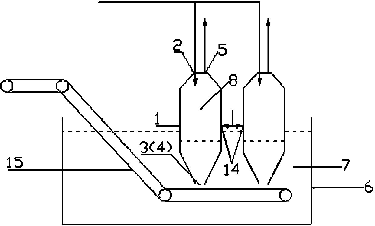
[0042] The forming device of the liquid residue of the present invention, such as figure 1 As shown, it includes a cooling tower 1, the top is provided with a liquid residue inlet 2 (also can be arranged in the upper part), the bottom is provided with a liquid residue outlet 3 (also can be arranged in the lower part), and a first coolant inlet 4 and a gas outlet are also provided. 5. The positions of the first coolant inlet 4 and the gas outlet 5 can be selected. In this embodiment, the first coolant inlet 4 is set at the bottom of the cooling tower 1 (it can also be set at the bottom), so The gas outlet 5 is set on the top of the cooling tower 1 (it can also be set on the upper part); the first coolant inlet 4 can be selected to communicate with or not communicate with the inside of the forming tank 6. In this embodiment, the first A coolant inlet 4 communicates with the cavity 7 in the forming groove 6, the first coolant inlet 4 can be used as the liquid residue outlet 3;

...

Embodiment 2

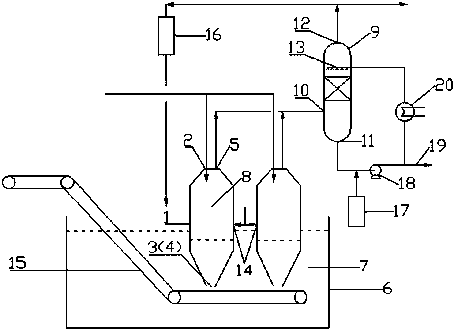
[0046] Based on the above, as a variable implementation method, such as figure 2 As shown, it also includes a washing tower 9, the lower part is provided with an air inlet 10 (also can be arranged at the bottom), the bottom is provided with a liquid outlet 11 (also can be arranged at the lower part), and the top is provided with an air outlet 12 (also can be arranged at the bottom) upper part); in the washing tower 9, a spray head 13 is arranged near the gas outlet 12; the air inlet 10 communicates with the gas outlet 5 of the cooling tower 1. In order to improve the heat exchange effect between the first coolant and the liquid residue, the lower part of the cooling tower 1 is provided with a ventilation hole 14 (it can also be arranged at the bottom), and the introduction of air into the ventilation hole 14 can accelerate the upward flow of the first coolant speed. Also includes an air cooler 16, the air cooler 16 is provided with a gas inlet and a water outlet, the gas inl...


PUM


Abstract

The invention discloses a forming device for liquid residues generated in a direct coal liquefaction process. The forming device comprises a cooling tower and a forming trough, wherein the top of the cooling tower is provided with a liquid residue inlet and a steam inlet, and the bottom of the cooling tower is provided with a liquid residue outlet and a steam outlet; and the forming trough is internally provided with a water storage space, and the liquid residue outlet is communicated with the water storage space in the forming trough. According to a use method of the forming device, high-temperature liquid residues are subjected to heat transfer with water vapor in the cooling tower so as to be pre-cooled and then flow into the water storage space of the forming trough to be cooled and formed underwater. The forming device disclosed by the invention is applicable to a pollution-free forming process for liquid residues obtained in the direct coal liquefaction process.

Description

technical field [0001] The invention relates to a method for forming liquid residue and a used forming device, belonging to the technical field of coal liquefaction. Background technique [0002] Coal direct liquefaction is a technology that directly converts coal into liquid fuel through catalytic hydrogenation under high temperature and high pressure. At present, a variety of coal direct liquefaction processes have been successfully developed in the world, including the German IGOR process, the American H-Coal process, and the Japanese NEDOL process. and China Shenhua Craft. [0003] The direct coal liquefaction process mainly includes a crushing and drying unit, a coal slurry preparation unit, a hydrogenation liquefaction unit, a solid-liquid separation unit and a liquid refining unit. Among them, the solid-liquid separation unit is a process of separating and treating the liquid fuel and liquid residue in the hydrogenation liquefaction product. In order to facilitate th...

Claims


Application Information

Patent Timeline
IPC IPC(8): B01J19/06C10G1/06
Inventor 井口宪二坂脇弘二
Owner 任相坤
Why Eureka
Try Eureka