Casting device with an annular duct and a casting method

A technology of annular pipes and molds, applied in the direction of casting molds, casting mold components, manufacturing tools, etc., can solve problems such as complex structures of casting devices, and achieve the effect of low cost and low quality

Inactive Publication Date: 2014-12-03
舒乐绞扭机有限责任公司
View PDF7 Cites 3 Cited by
  • Summary
  • Abstract
  • Description
  • Claims
  • Application Information

AI Technical Summary

Problems solved by technology

This gating system can fill the mold cavity evenly, but especially when using several molds, on the one hand it causes a complex construction of the casting device and on the other hand it requires that all the sprues have to be heated individually

Method used


Image

  • Casting device with an annular duct and a casting method
  • Casting device with an annular duct and a casting method
  • Casting device with an annular duct and a casting method

Examples


Embodiment Construction

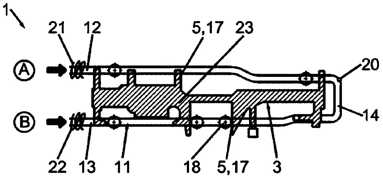
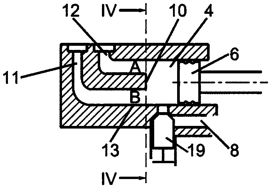
[0049] Figure 4 A part of a casting device 1 for die-casting molten metals such as molten magnesium or molten aluminum is shown. The melt 2 is guided from a melt reservoir 7 via a supply line 8 which can be blocked by means of a melt valve 19 into a casting chamber 4 . The casting chamber 4 is oriented horizontally and can be moved by a hydraulically moved casting piston 6 ( image 3 ) pressure loading. On the end side 10 opposite the casting piston 6 , the casting chamber 4 has exactly two annular line connections A and B, which form the ends of the annular line 11 .

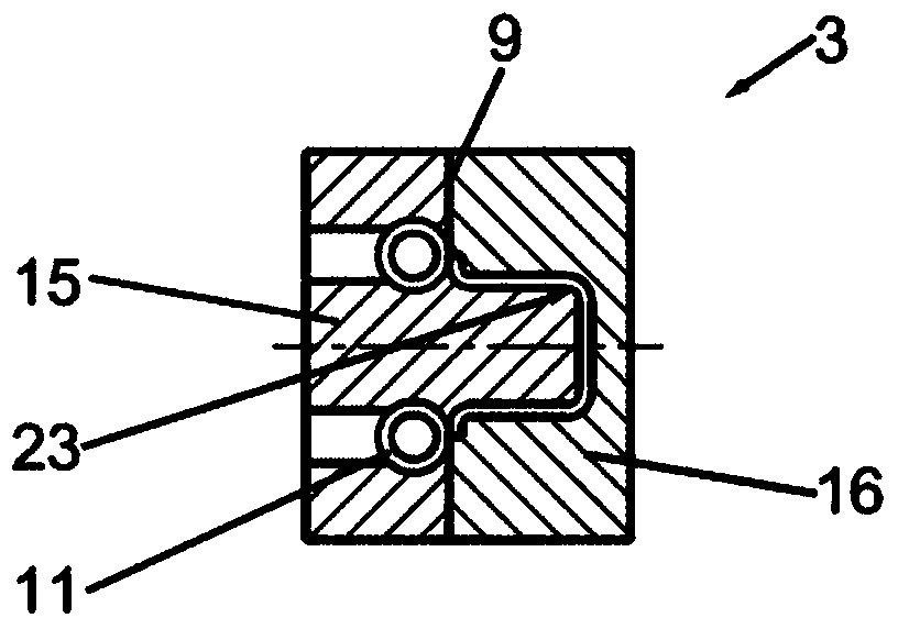
[0050] Such as figure 1 As shown, the annular duct 11 is guided in the vicinity of the tool cavity 3 and is formed by two essentially parallel, pressure-resistant connecting channels 12 , 13 . The connecting channels 12 , 13 open into the casting chamber 4 in annular line connections A and B, wherein the annular line connection A is arranged above the annular line connection B. The connecting channels 12 ...


PUM


Abstract

A casting device includes a mold cavity configured to form a hollow space for a cast part, a casting chamber for a metal melt, a gating system, an annular duct for the metal melt, and at least two annular duct connections configured to connect the casting chamber to the annular duct. The annular duct is configured to be connectable with the mold cavity via the gating system.

Description

technical field [0001] The invention relates to a casting device comprising: a mold cavity forming a hollow space for a cast part; a casting chamber for a molten metal; and a casting system. The invention also relates to a casting method for producing castings with the casting device. Background technique [0002] For casting defined melts, especially when the melt is in metallic form, a lot of heat is given off into its surroundings. In order to achieve good casting quality, too intensive cooling must be avoided during the casting process. For this purpose, the casting is performed in a cold cavity die casting method with high speed and high pressure. The mold filling process of the injection mold forming the mold cavity typically lasts a few milliseconds depending on the size of the cast part and its minimum wall thickness. [0003] A defined gating speed (Anschnittgeschwindigkeiten) and gating system are suitable for each melt type. Since a maximum sprue speed must no...

Claims


Application Information

Patent Timeline
Patent Type & Authority Applications(China)
IPC IPC(8): B22D17/30
CPCB22D17/2023B22D17/22B22D17/30B22C9/08
Inventor M·格布格斯J·法伦巴赫T·施瓦茨
Owner 舒乐绞扭机有限责任公司
Why Eureka
Try Eureka