An antenna oscillator automatic welding equipment

An antenna vibrator, automatic welding technology, applied in welding equipment, metal processing equipment, tin feeding devices, etc., can solve the problems of poor product consistency, high labor cost, poor product stability, etc., and achieve high product consistency and stability. The effect of low labor cost and high welding efficiency

Inactive Publication Date: 2016-04-20
HUIZHOU SANLI ENTERPRISE
View PDF6 Cites 0 Cited by
  • Summary
  • Abstract
  • Description
  • Claims
  • Application Information

AI Technical Summary

Problems solved by technology

[0002]The four corners of each antenna vibrator need to be welded, and the position of each corner has a first welding point and a second welding point that need to be welded respectively. At present, the antenna vibrator Welding On the one hand, manually hold the antenna vibrator, first contact the first welding point on one corner of the antenna vibrator with the high-frequency welding equipment to heat the part of the antenna vibrator to be welded (the first welding point), on the other hand, manually at a constant speed Send the tin wire from the center of the welding pipe induction area of ​​the high-frequency welding equipment to the tin area on the antenna vibrator to be welded (the first soldering point), then manually remove the unused tin wire, and then connect the second soldering point on one corner of the antenna vibrator with the The high-frequency welding equipment makes contact to heat the part of the antenna vibrator to be welded (the second welding point), and then artificially sends the tin wire and the tin area of ​​the antenna vibrator to be welded (the second welding point) in the center of the induction area of ​​the high-frequency welding equipment at a uniform speed. The above links are all manually operated by the antenna vibrator in contact with the high-frequency welding equipment, and the tin feeding line is manually sent to the high-frequency welding equipment welding pipe induction center to the tinning area on the antenna vibrator. This manual operation welding has the following disadvantages: 1. Poor product consistency; 2. Poor product stability; 3. Low one-time pass rate; 4. Low welding efficiency of antenna vibrators; 5. Not suitable for batch operations;

Method used


Image

  • An antenna oscillator automatic welding equipment
  • An antenna oscillator automatic welding equipment

Examples


Embodiment Construction

[0023] In order to facilitate the understanding of those skilled in the art, the structural principles of the present invention will be further described in detail below in conjunction with specific embodiments and accompanying drawings.

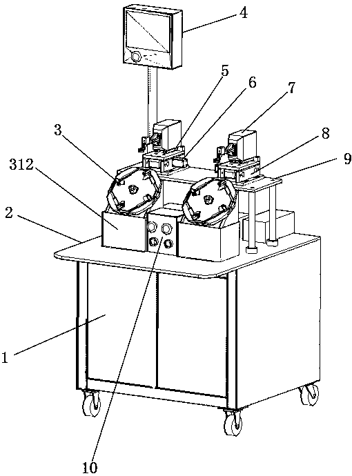
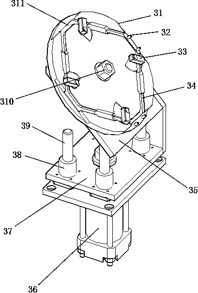
[0024] Such as figure 1 , figure 2 As shown, an antenna vibrator automatic welding equipment includes a chassis 1, the top of the chassis 1 is a working platform 2, the upper left of the chassis 1 is provided with an electric control box 4, and the working platform 2 is provided with a welding mechanism. The welding mechanism includes antenna vibrator fixture assembly 3, high-frequency induction welding machine 7, placing workbench 9, mobile adjustment mechanism and automatic tin feeding mechanism, and the rear of antenna vibrator fixture assembly 3 is provided with placing workbench 9, and placing workbench 9 is provided with a mobile adjustment mechanism, and the mobile adjustment mechanism is provided with a high-frequency induction we...


PUM


Abstract

The invention discloses an antenna vibrator automatic welding device, which comprises a case, the upper part of the case is a working platform, an electric control box is arranged on the upper left side of the case, a welding mechanism is arranged on the working platform, and the welding mechanism includes an antenna Vibrator fixture assembly, high-frequency induction welding machine, placing workbench, mobile adjustment mechanism and automatic tin feeding mechanism, the rear of the antenna vibrator fixture assembly is equipped with a placement worktable, and the placement workbench is equipped with a mobile adjustment mechanism and a mobile adjustment mechanism There is a high-frequency induction welding machine on the top. The high-frequency induction welding machine is controlled by a mobile adjustment mechanism to adjust the left and right positions. The working platform below the workbench is equipped with an automatic tin feeding mechanism. The automatic tin feeding mechanism includes the first tin feeding mechanism and The second tin feeding mechanism, the first tin feeding mechanism and the second tin feeding mechanism are respectively used for soldering the first soldering point and the second soldering point on the antenna vibrator. The invention has the advantages of high welding efficiency, high first pass rate, stable output and labor cost saving.

Description

technical field [0001] The invention relates to the welding of antenna oscillators, in particular to an automatic welding equipment for antenna oscillators. Background technique [0002] The four corners of each antenna vibrator need to be welded, and the position of each corner has a first welding point and a second welding point that need to be welded respectively. At present, on the one hand, the antenna vibrator is welded manually by manually holding the antenna vibrator. The first welding point on one corner is in contact with the high-frequency welding equipment to heat the part of the antenna vibrator to be welded (the first welding point). Solder (the first soldering point) the upper tin area, then manually remove the unused tin wire, and then contact the second soldering point on one corner of the antenna vibrator with the high-frequency welding equipment to heat the antenna vibrator to be welded ( The second welding point), and then artificially send the tin wire ...

Claims


Application Information

Patent Timeline
Patent Type & Authority Patents(China)
IPC IPC(8): B23K3/00B23K3/08
CPCB23K1/0008B23K1/002B23K3/00B23K3/063B23K3/08B23K3/087
Inventor 朱建波温伟峰
Owner HUIZHOU SANLI ENTERPRISE
Why Eureka
Try Eureka