
laser processing machine

A laser processing machine, laser technology, applied in the direction of metal processing, laser welding equipment, metal processing equipment, etc., can solve the problems of time-consuming and long time, and achieve the effect of eliminating waste, shortening time, and shortening processing time

Active Publication Date: 2018-01-09
SUMITOMO HEAVY IND LTD
View PDF10 Cites 0 Cited by
  • Summary
  • Abstract
  • Description
  • Claims
  • Application Information

AI Technical Summary

Problems solved by technology

[0008] However, when changing the fixing jig attached to the laser processing machine according to the type of processing object, it is necessary to attach and detach the fixing jig dedicated to the workpiece with a frame and the fixing jig dedicated to the thin plate, and it takes time to install the workpiece with a frame or the thin plate accordingly. The problem
In addition, when the size of the framed workpiece changes, the position of the thin plate attached to the framed workpiece also changes along with the change. Therefore, it takes a long time to detect the processing base point on the thin plate. The problem that the processing takes time
Furthermore, when machining a workpiece with a frame, if the sensor detects the frame and the fixing jig, the machining is stopped. Therefore, it is necessary to change the machining object again and re-machining from the beginning. Accordingly, there is a problem that it takes time until the machining is completed.

Method used


Image

  • laser processing machine
  • laser processing machine
  • laser processing machine

Examples


Embodiment Construction

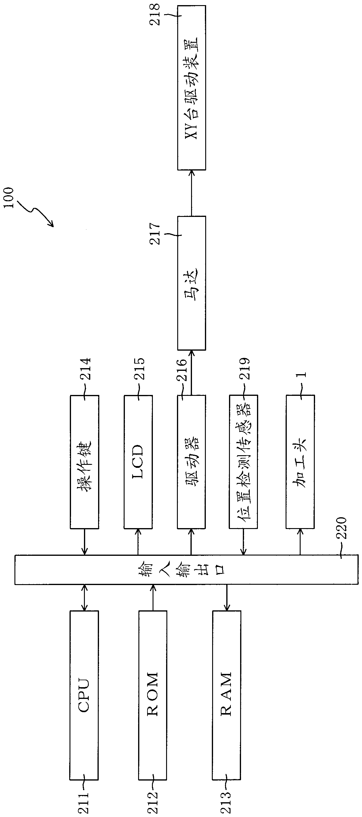
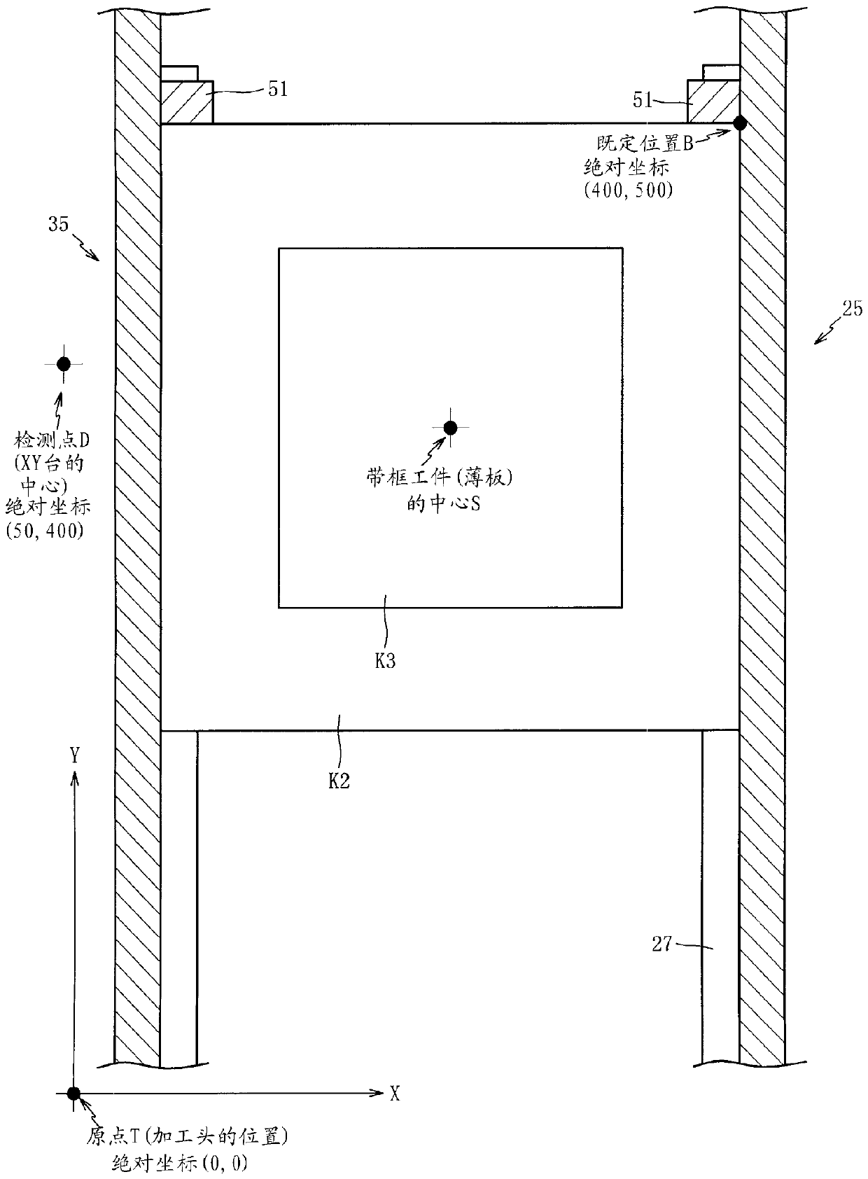
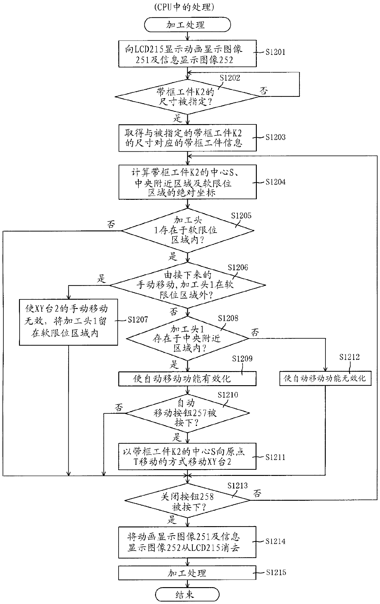
[0033]Next, embodiments of the laser processing machine of the present invention will be described below with reference to the drawings. First, refer to Figure 1 to Figure 4 The laser processing machine 100 of the first embodiment will be described. figure 1 It is a figure which schematically shows the main structure of the laser processing machine 100 of 1st Embodiment. The laser processing machine 100 processes a stainless steel plate that is masked to apply the solder only to necessary portions of the substrate when applying solder to a substrate of an electronic component.

[0034] The stainless steel plate is attached to the mirror-frame-shaped frame to cover and mask the electronic substrate, so the stainless steel plate needs to be attached to the frame. As a method of attaching the stainless steel plate to the frame, there are mainly two methods of attaching the processed stainless steel plate to the frame and attaching the unprocessed stainless steel plate to the f...


PUM


Abstract

The invention provides a laser processing machine capable of shortening the processing time containing processing object setting time in order to process a framed workpiece or sheet as a processing object. A framed workpiece clamp (10) of a retention framed workpiece (K2) can be detachably and freely arranged between a sheet clamp (3) of a retention sheet (K1). Before processing, the processing object is confirmed to be the framed workpiece (K2) or the sheet (K1). When the framed workpiece (K2) is processed, a processing area which is not in contact with a frame body of the framed workpiece (K2) is calculated, and the processing is carried out in the processing area.

Description

technical field [0001] The present invention relates to a laser processing machine, and particularly to a laser processing machine capable of shortening the processing time including the time for setting the processing object for processing a framed workpiece or a thin plate as the processing object. Background technique [0002] In conventional laser processing machines, dedicated fixing jigs are used depending on the type of processing object (thin plate, framed workpiece with a thin plate attached to a mirror-frame-shaped frame) in order to ensure processing accuracy. For example, Japanese Patent Application Laid-Open No. 2002-205182 describes the technology of a laser processing machine equipped with a fixed jig dedicated to a workpiece with a frame (Patent Document 1), and Japanese Patent Laid-Open No. 2002-248588 describes a laser processing machine equipped with a thin plate Technology of a laser processing machine with a dedicated fixed jig (Patent Document 2). [0...

Claims


Application Information

Patent Timeline
Patent Type & Authority Patents(China)
IPC IPC(8): B23K26/03B23K26/70B23K37/04
CPCB23K26/03B23K26/0853B23K37/0408B23K2101/18B23K2103/04
Inventor 藤泽佳生古田泰之
Owner SUMITOMO HEAVY IND LTD
Learn More