Tail yarn head keeping device for tail yarn removing machine

A technology for clearing machine and tail yarn, which is applied in the direction of transportation and packaging, delivery of filamentous materials, thin material processing, etc. problems, achieve good twist breaking and loosening effect, improve removal efficiency, and ensure spinning quality

Active Publication Date: 2014-12-03
TIANJIN HONGDA TEXTILE MACHINERY
View PDF6 Cites 4 Cited by
  • Summary
  • Abstract
  • Description
  • Claims
  • Application Information

AI Technical Summary

Problems solved by technology

The tail yarn cleaning machine is mainly used in the thick and fine joint system to automatically remove the tail yarn on the roving bobbins used by the spinning frame and the waste flowers adsorbed on the sticky strips, and then through the automatic conveying system for the automatic spinning of the roving frame Direct use, although the tail yarn removal machine can save labor and improve production efficiency, however, in the actual operation process, some tail yarn bobbins often cause longer tail yarn ends due to operational reasons or the weight of the yarn. Such a bobbin directly enters the tail yarn removal machine, and problems such as tail yarn winding on the spindle rod and yarn pressing may occur, or the tail yarn removal machine suction pipe cannot find the tail yarn end due to the limited up and down motion of the machine itself, resulting in The tail yarn cannot be cleaned, reducing the success rate of the tail yarn removal machine to remove the tail yarn, and affecting the subsequent operation and use
[0003] At present, in order to solve the problem that the removal efficiency is affected by the excessive length of tail yarn end, the pressure generated by the fan is usually used to suck and break the excessively long tail yarn. However, because the pressure generated by the fan is limited by the speed and power of the fan, the pressure generated Limited, and because the fan is always running, the power consumption is also very large
In addition, the effect of breaking the twist and loosening the sucked tail yarn through the rotation of the fan is not very ideal.

Method used


Image

  • Tail yarn head keeping device for tail yarn removing machine
  • Tail yarn head keeping device for tail yarn removing machine
  • Tail yarn head keeping device for tail yarn removing machine

Examples


Embodiment Construction

[0017] The present invention will be further described in detail below in conjunction with the accompanying drawings and specific embodiments, but the present invention is not limited to these embodiments.

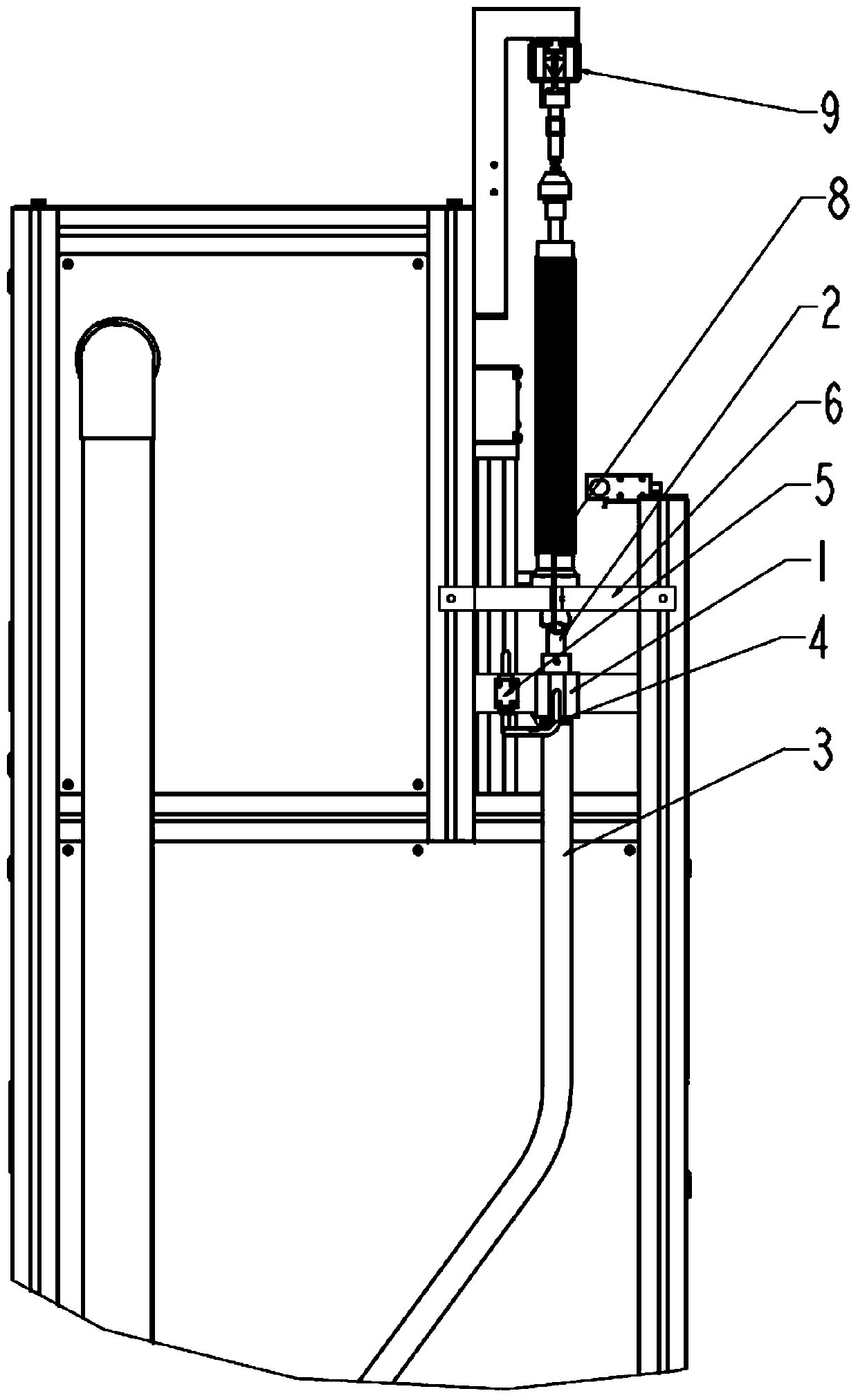
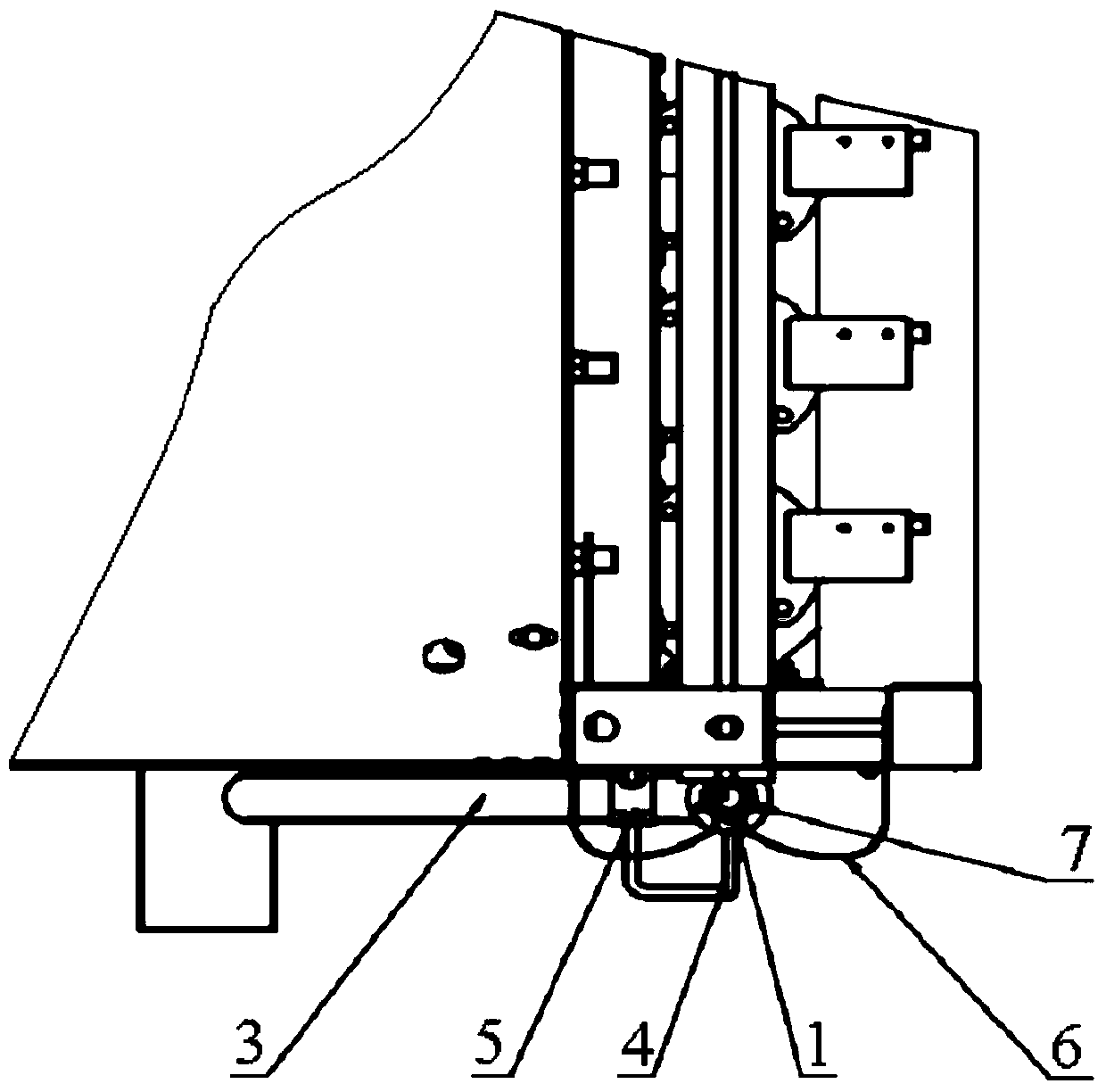
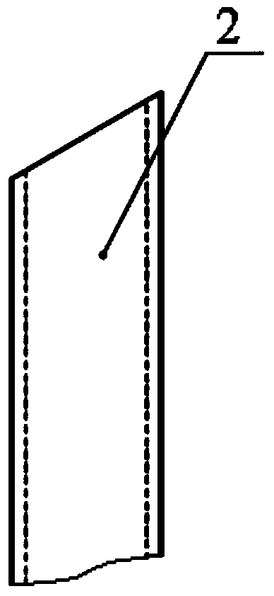
[0018] Such as figure 1 with figure 2 As shown, the present invention is a tail yarn removal device for a tail yarn retention device, which includes a suction device, a driving device and a detection device. The suction device includes a negative pressure chamber 1, a suction pipe 2, an exhaust pipe 3, an air pipe 4 and a yarn guide plate 6, and the negative pressure chamber 1 is fixedly installed on a frame at the entrance side of the tail yarn removal machine. The lower end of the suction pipe 2 communicates with the negative pressure chamber 1, such as Figure 3-1 with Figure 3-2 As shown, the suction pipe 2 is a circular tube, and the upper end is a port with a slope. In use, the port faces the side of the bobbin tube 8 with tail yarn, and the port of the upper en...


PUM


Abstract

The invention discloses a yarn head keeping device for a tail yarn removing machine. The yarn head keeping device comprises a sucking and breaking device, a driving device and a detecting device, wherein the sucking and breaking device comprises a negative pressure bin, a suction pipe, an exhaust pipe, an air pipe and a yarn guide plate; the negative pressure bin is fixedly mounted on a rack on one side at the inlet of the tail yarn removing machine; the lower end of the suction pipe is communicated with the negative pressure bin; the upper end of the suction pipe faces one side of a bobbin with the tail yarn; the two ends of the exhaust pipe are connected with the negative pressure bin and a lap waste box respectively; the two ends of the air pipe are connected with the negative pressure bin and the driving device respectively; the yarn guide plate is fixed on the rack on one side at the inlet of the tail yarn removing machine and positioned between the negative pressure bin and the bottom of the bobbin; the driving device comprises a two-way electromagnetic valve; the two-way electromagnetic valve is connected with the air pipe and a gas source respectively; the detection device comprises an optical fiber amplifier fixed at the lower part of the yarn guide plate. According to the tail yarn head keeping device, the lengths of kept tail yarn heads on the bobbin are basically consistent, the broken yarn heads can be conveniently found by the tail yarn removing machine, the tail yarn removing efficiency is improved and the spinning quality is guaranteed.

Description

technical field [0001] The invention belongs to the field of textile machinery, in particular to a tail yarn removing machine device. Background technique [0002] With the improvement of the degree of automation of textile machinery and the wide application of thickness and fineness equipment, the cleaning of empty bobbins and tail yarns has become more and more important, so tail yarn removal machines have appeared on the market. The tail yarn cleaning machine is mainly used in the thick and fine joint system to automatically remove the tail yarn on the roving bobbins used by the spinning frame and the waste flowers adsorbed on the sticky strips, and then through the automatic conveying system for the automatic spinning of the roving frame Direct use, although the tail yarn removal machine can save labor and improve production efficiency, however, in the actual operation process, some tail yarn bobbins often cause longer tail yarn ends due to operational reasons or the wei...

Claims


Application Information

Patent Timeline
IPC IPC(8): B65H73/00
Inventor 张淑红邢承凤贾秀华陈伟龙
Owner TIANJIN HONGDA TEXTILE MACHINERY
Why Eureka
Try Eureka