Ceiling structure with arc and manufacturing and mounting method thereof

A technology for a ceiling structure and an installation method, which is applied to building structures, building components, buildings, etc., can solve the problems of low production efficiency, increased overall cost of ceilings, and cumbersome installation, and achieves small occupied space and low overall cost. Easy to transport and install

Active Publication Date: 2014-12-03
GUANGZHOU COMPTON ZHIGAO BUILDING MATERIALS
5 Cites 2 Cited by

AI-Extracted Technical Summary

Problems solved by technology

In the prior art, in order to meet the aesthetic requirements of some customers, manufacturers are required to manufacture a curved ceiling structure. This kind of curved ceiling structure requires a variety of metal plates with different curved lines, which not only complicates the production process, but also The efficiency is low, and this kind of metal plate is relatively thick (to ensure...

Method used

As shown in Fig. 1, Fig. 2, Fig. 3, Fig. 4, the present invention comprises band arc ceiling unit 1, support rod 2, keel 3 and suspender 4, and described band arc ceiling unit 1 is made of several blocks A combination of single-piece punched plates 6 with a wavy side length section, the specific number of the single-piece punched plates 6 is determined according to the actual size of the ceiling. In the curved ceiling unit 1, the single punching plates 6 are arranged in such a way that the arc surfaces are tangent to the arc surfaces, and the arc surfaces between the single punch plates 6 are tangent to each other. The connecting agent layer 7 is adhered to each other, and the lower end of the rod body of the support rod 2 is radially provided with a groove matching the single-piece punching plate 6. The width of the groove is three millimeters, and the single-piece punching plate The arc surface between 6 is disposed in the groove tangent to the arc surface, the inside of the support rod 2 is hollow and a metal wire 5 is provided, and one end I of the metal wire 5 is bent and hung on the upper end of the support rod 2 On the outer wall, the other end II of the metal wire 5 extends along the inner wa...

Abstract

The invention discloses and provides a ceiling structure with an arc, which is shaped like a metal colored ribbon, attractive in appearance, simple and convenient to transport and mount and low in the total cost, and a manufacturing and mounting method of the ceiling structure. The manufacturing and mounting method of the ceiling structure with the arc is completed through prefabrication in a factory and mounting in a construction site. The ceiling structure with the arc comprises ceiling units (1) with arcs, a supporting rod (2), a keel (3) and a suspending rod (4), wherein a metal wire (5) is arranged inside the supporting rod (2); the supporting rod (2) is connected with the ceiling units (1) with the arcs through the metal wire (5); one end of the supporting rod (2) is connected with the keel (3); the keel (3) is connected with the suspending rod (4); therefore, the ceiling units (1) with the arcs, the supporting rod (2), the keel (3) and the suspending rod are combined into the ceiling structure. The ceiling structure is mainly applied to the field of suspended ceilings.

Application Domain

CeilingsBuilding material handling

Technology Topic

MetalPrefabrication +3

Image

  • Ceiling structure with arc and manufacturing and mounting method thereof
  • Ceiling structure with arc and manufacturing and mounting method thereof
  • Ceiling structure with arc and manufacturing and mounting method thereof

Examples

  • Experimental program(1)

Example Embodiment

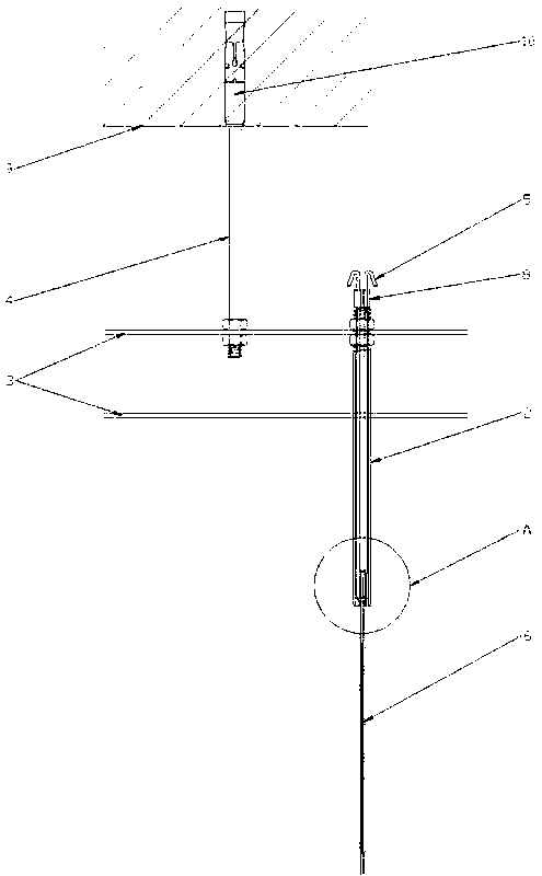
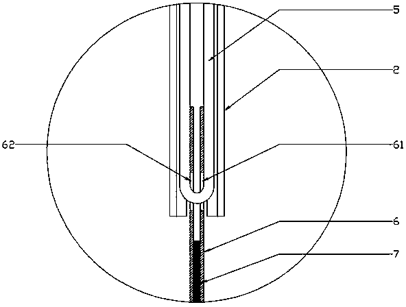
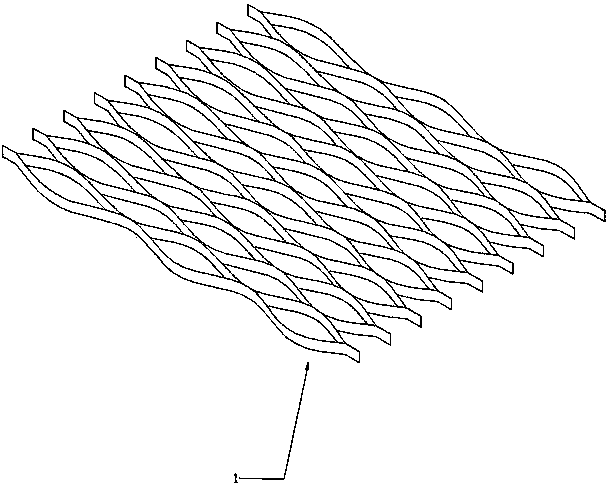
[0028] Such as figure 1 , figure 2 , image 3 , Figure 4 As shown, the present invention includes a curved ceiling unit 1, a support rod 2, a keel 3, and a boom 4. The curved ceiling unit 1 is composed of a plurality of single-piece punching plates 6 with a wave-shaped side length section. Therefore, the specific number of the single-piece punching plate 6 is determined according to the actual size of the ceiling. In the curved ceiling unit 1, the single-piece punching plates 6 are arranged in such a way that the arc surface is tangent to the arc surface, and the arc surface and the arc surface tangent between the single-piece punching plates 6 pass through The connecting agent layer 7 is adhered, and the lower end of the rod body of the support rod 2 is radially provided with a groove matching the single-piece punching plate 6. The width of the groove is three millimeters, and the single-piece punching plate The arc surface between 6 and the arc surface are disposed tangentially in the groove. The support rod 2 is hollow and provided with a wire 5, one end I of the wire 5 is bent and hung on the upper end of the support rod 2. On the outer wall, the other end II of the wire 5 extends along the inner wall of the support rod 2 to the lower end of the support rod 2 and passes through the holes 61 and 62 of the single-piece punching plate 6 in sequence. The end II is then folded back along the inner wall of the support rod 2 to the upper end of the support rod 2, and is fixed to the support by a metal lock 8 with a diameter larger than the inner diameter of the support rod 2 together with the end I The upper end of the rod 2 thus realizes the connection between the supporting rod 2 and the curved ceiling unit 1. In addition, the connection between the supporting rod 2 and the curved ceiling unit 1 can also be achieved in other ways, such as It is directly fixed by means of bolts or nuts, etc., but the method of passing through the metal wire is relatively simple and beautiful. The present invention adjusts the extension length of the metal wire 5, and then adjusts the height of the single-piece punching plate 6 relative to the ground, so as to realize the bottom surface of the curved ceiling unit 1 and then present an undulating belt arc Line shape. In the present invention, the metal wire 5 plays the role of hanging and bearing, and the support rod 2 plays the role of positioning and supporting the horizontal plane.
[0029] The upper end of the support rod 2 is externally threaded and passes through the upper and lower end surfaces of the keel 3, and the support rod 2 is fixed to the support rod 2 by two nuts I that match the upper end of the support rod 2. The upper end of keel 3. The lower end of the boom 4 is threaded and passes through the upper end surface of the keel 3, and the boom 4 is fixed to the upper end surface of the keel 3 by two nuts II matching the lower end of the boom 4, An expansion screw 10 is provided at the upper end of the suspension rod 4, and the suspension rod 4 is fixed to the ceiling carrier 9 by the expansion screw 10.
[0030] The present invention is described in detail by using metal wire fixation as a preferred solution. The manufacturing and installation method of the present invention is prefabricated in the factory and installed on the construction site. The manufacturing and installation method includes the following steps:
[0031] ① Prepare the curved ceiling unit 1, support rod 2, keel 3, and boom 4 in the factory. The keel 3 is provided with through holes at equal intervals, wherein the curved ceiling unit 1 includes a number of single pieces Punching plate group, the single-piece punching plate group is formed by bonding two single-piece punching plates 6, the distance between the bonding points on the single-piece punching plate group and the support rod 2 The distances on the keels 3 are equal, and the positions of the bonding points between the single-piece punching plates 6 and the bonding points between the single-piece punching plate groups are staggered. As a preferred solution, The position of the bonding point between the single-piece punching plate group is located at the tangent point of the single-piece punching plate 6 in an arc segment (the highest point on the outer surface);
[0032] ② Stretch and unfold an appropriate number of the curved ceiling units 1 on site according to the area requirements, and connect a plurality of the curved ceiling units 1 to form a combined overall ceiling structure, from top to bottom Fix the boom 4, the keel 3 and the support rod 2;
[0033] ③"After hoisting the curved ceiling unit 1, the metal wire 5 is passed through the curved ceiling unit 1, and then the metal wire 5 is connected and fixed to the support rod 2.
[0034] Wherein, the step of preparing the curved ceiling unit 1 in step ① includes:
[0035] a. Unloading, slitting the aluminum coil into coils of appropriate width;
[0036] b. Punching, continuous punching line for the cut roll material, and automatically cut into equal width blanks according to the design length;
[0037] c. Leveling, the rough part is leveled for the first time through the leveling equipment;
[0038] d. Spraying, the blank after the first leveling is cleaned by pretreatment and then hung and sprayed to obtain the single-piece punching plate 6. The spraying method can be electrostatic powder spraying or fluorocarbon Spraying
[0039] e. Leveling, the single-piece punching plate 6 after spraying is leveled for the second time by leveling equipment;
[0040] f. Bonding, according to the designed grid size and bonding position, the two single-piece punching plates 6 are bonded into a single-piece punching plate group with tape, and then a group of multiple The single-piece punching plate group is bonded by tape to form the curved ceiling unit 1, and the bonding points of the single-piece punching plate group and the bonding points of the curved ceiling unit 1 are staggered equidistantly.
[0041] The preparation step of the keel 3 in the step ① includes: using a steel coil to continuously punch and shape, and then perform a cutting treatment, and then perform a spraying treatment. The through holes on the upper and lower sides of the steel coil need to be aligned to The support rod 2 can pass vertically.
[0042] The invention is suitable for the field of ceiling suspended ceilings.

PUM

no PUM

Description & Claims & Application Information

We can also present the details of the Description, Claims and Application information to help users get a comprehensive understanding of the technical details of the patent, such as background art, summary of invention, brief description of drawings, description of embodiments, and other original content. On the other hand, users can also determine the specific scope of protection of the technology through the list of claims; as well as understand the changes in the life cycle of the technology with the presentation of the patent timeline. Login to view more.

Similar technology patents

Automatic box making device and method

ActiveCN105235278AImprove processing speed and productivitysmall footprint
Owner:中科天工(广东)智能技术有限公司

A slide rail assembly machine

Owner:GUANGDONG SACA PRECISION MFG CO LTD

Multistage integrated hydrodynamic cyclone separator

InactiveCN102512857ASmall footprintEasy to install and control
Owner:BEIJING UNIVERSITY OF CIVIL ENGINEERING AND ARCHITECTURE

Garbage leachate advanced treatment method and Fenton reaction tower

ActiveCN103880253ASmall footprintLess investment in infrastructure
Owner:深圳市百斯特环保工程有限公司

Automatic processing production line for metal sheets

ActiveCN105458718ASmall footprintReasonable production beat matching
Owner:江苏扬力数控机床有限公司

Classification and recommendation of technical efficacy words

  • Small footprint
  • Easy to install

Cooking electric appliance

PendingCN107647763AEasy to installAvoid insulation loss
Owner:FOSHAN SHUNDE MIDEA ELECTRICAL HEATING APPLIANCES MFG CO LTD

System for monitoring vibration of rotating machinery rolling bearing in wireless mode

InactiveCN102053016Ameasurementanalysisdatareal-timeEasy to install
Owner:JIANGSU UNIV
Why Eureka
Try Eureka