Signal acquisition device based on experiments of laser-induced ignition of solid propellants

A solid propellant, laser ignition technology, applied in the field of signal testing research, can solve problems such as large error and limited measurement accuracy, and achieve the effects of low cost, simple construction and operation, and simple principle

Active Publication Date: 2014-12-03
NANJING UNIV OF SCI & TECH
View PDF5 Cites 18 Cited by
  • Summary
  • Abstract
  • Description
  • Claims
  • Application Information

AI Technical Summary

Problems solved by technology

The disadvantage of this method is that the measurement accuracy is limited by the frame rate of the video equipment, and the two-frame images of the initi

Method used


Image

  • Signal acquisition device based on experiments of laser-induced ignition of solid propellants

Examples


Embodiment 1

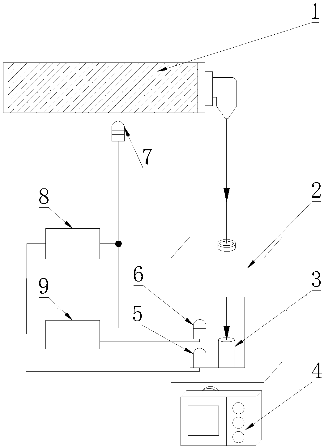
[0020] A signal acquisition device based on a solid propellant laser ignition experiment, comprising a high-speed camera 4, a light-emitting diode 5, a photodiode 6 for flame, a photodiode 7 for laser, an amplifier circuit 8 and a data acquisition card 9; the photodiode 7 for laser and The tube wall of laser tube 1 is close to, and the flame photodiode 6 is arranged on the outside of the window of the combustion chamber 2, and corresponds to the window position, and the photosensitive surface of the flame photodiode 6 is horizontally aligned with the top surface of the solid propellant sample 3, The input end of amplifier circuit 8 is connected with photodiode 7 for laser, the output end of amplifier circuit 8 is connected with light-emitting diode 5, and light-emitting diode 5 is arranged in the available angle of view of high-speed camera 4, and high-speed camera 4 is arranged on the window of combustion chamber 2 External, and corresponding to the window position; the signal...

Embodiment 2

[0026] combine figure 1 :

[0027] A signal acquisition device based on a solid propellant laser ignition experiment, comprising a high-speed camera 4, a light-emitting diode 5, a photodiode 6 for flame, a photodiode 7 for laser, an amplifier circuit 8 and a data acquisition card 9; the photodiode 7 for laser and 0.2m away from the wall of the laser tube 1, the photodiode 6 for the flame is arranged outside the window of the combustion chamber 2, and corresponds to the position of the window. The photosensitive surface of the photodiode 6 for the flame is horizontally aligned with the top surface of the solid propellant sample 3, The input end of amplifier circuit 8 is connected with photodiode 7 for laser, the output end of amplifier circuit 8 is connected with light-emitting diode 5, and light-emitting diode 5 is arranged in the available angle of view of high-speed camera 4, and high-speed camera 4 is arranged on the window of combustion chamber 2 External, and correspondi...


PUM


Abstract

The invention discloses a signal acquisition device based on experiments of laser-induced ignition of solid propellants. The signal acquisition device comprises image recording equipment, a light-emitting diode, a flame photodiode, a laser photodiode, an amplifying circuit and a data acquisition card, wherein the laser photodiode is close to the wall of a laser tube; the flame photodiode is arranged outside a view window of a combustion chamber and is in positional correspondence with the view window; an input end of the amplifying circuit is connected with the laser photodiode, and an output end of the amplifying circuit is connected with the light-emitting diode; the light-emitting diode is arranged in a photographable visual angle of the image recording equipment, and the image recording equipment is arranged outside the view window of the combustion chamber and is in positional correspondence with the view window; a signal input end of the data acquisition card is connected with the laser photodiode and the flame photodiode. The signal acquisition device is simple in principle, high in precision and reasonable in cost and is convenient to operate.

Description

technical field [0001] The invention belongs to the technical field of signal testing and research, in particular to a signal acquisition device based on a solid propellant laser ignition experiment. Background technique [0002] The traditional solid propellant ignition generally adopts an igniter equipped with igniting powder, uses an electrode to detonate the igniting powder in the igniter, and takes the moment when the power switch is turned on to energize the electrode as the initial moment. The research on the ignition of solid propellants under laser irradiation began in the 1960s. Due to the novelty of the ignition method, the traditional method of measuring the ignition delay time is no longer applicable. The measurement of the ignition delay time in the laser ignition experiment is to take the moment when the gas in the laser tube emits laser light after the voltage is broken down as the initial moment. In the large amount of literature on laser ignition, there is...

Claims


Application Information

Patent Timeline
IPC IPC(8): G01N21/84
Inventor 王鸿美陈雄许进升郑健周长省
Owner NANJING UNIV OF SCI & TECH
Why Eureka
Try Eureka