
Device for measuring rotating speed of motor and electronic equipment

A technology for measuring device and motor speed, applied in the circuit field, can solve problems such as low test efficiency and inaccurate test, and achieve the effect of solving low test efficiency, inaccurate test data, and simple and reliable measurement method

Inactive Publication Date: 2014-12-03
SHENZHEN OCEANS KING LIGHTING ENG CO LTD +1
View PDF6 Cites 5 Cited by
  • Summary
  • Abstract
  • Description
  • Claims
  • Application Information

AI Technical Summary

Problems solved by technology

It can solve the shortcomings of low test efficiency and inaccurate test in the prior art

Method used


Image

  • Device for measuring rotating speed of motor and electronic equipment
  • Device for measuring rotating speed of motor and electronic equipment

Examples


Embodiment Construction

[0012] The following will clearly and completely describe the technical solutions in the embodiments of the present invention with reference to the accompanying drawings in the embodiments of the present invention. Obviously, the described embodiments are only some, not all, embodiments of the present invention. Based on the embodiments of the present invention, all other embodiments obtained by persons of ordinary skill in the art without creative efforts fall within the protection scope of the present invention.

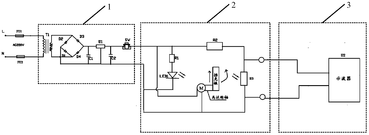
[0013] see figure 1 , is a structural schematic diagram of a motor speed measuring device according to an embodiment of the present invention, hereinafter referred to as the measuring device. The measuring device includes a DC voltage stabilizing circuit 1, a photoelectric conversion circuit 2 and a frequency measuring circuit 3. The circuit 2 is connected with the frequency measurement circuit 3, and the DC voltage stabilizing circuit 1 converts the AC power outpu...


PUM


Abstract

The embodiment of the invention discloses a device for measuring the rotating speed of a motor. The device includes a direct current voltage-stabilizing circuit, a photoelectric conversion circuit and a frequency measuring circuit, and the direct current voltage-stabilizing circuit is connected with the frequency measuring circuit via the photoelectric conversion circuit; and the direct current voltage-stabilizing circuit is used for converting alternating voltage input by an external alternating current power supply to supply power to the device for measuring the rotating speed of the motor, the photoelectric conversion circuit includes a light barrier, a light-emitting diode and a photoresistor, wherein the light barrier is mounted on a rotating shaft of the motor, the light-emitting diode, the motor and the photoresistor are on the same straight line, so that when driving the light barrier to rotate, the motor can periodically cut off light irradiated to the photoresistor by the light-emitting diode to generate a periodic pulse optical signal, the photoelectric conversion circuit converts the pulse optical signal to a pulse electrical signal, and the frequency measuring circuit is used for measuring the frequency of the pulse electrical signal. The embodiment of the invention also discloses electronic equipment. The device for measuring the rotating speed of the motor in the invention has the advantages of high test efficiency and accurate test results.

Description

technical field [0001] The invention relates to the field of circuits, in particular to a motor speed measuring device and electronic equipment. Background technique [0002] As a power generation device, the motor is widely used in all walks of life. In some applications, we need to test the reliability of the motor, such as measuring the motor speed and other parameters, to check whether the motor speed meets the requirements during the design process. Usually The test method is to set a baffle on the rotating shaft connected to the motor, mark it on the baffle, energize the motor to rotate, count the number of turns of the motor within 1 minute during the rotation, and divide by the number of turns The rotation speed of the motor is obtained in 1 minute, but when the rotating speed of the motor shaft under test is relatively fast, it is impossible to know the number of rotations of the motor, and the rotation speed of the motor cannot be calculated, and the test method is...

Claims


Application Information

Patent Timeline
Patent Type & Authority Applications(China)
IPC IPC(8): G01P3/36
Inventor 周明杰胡波
Owner SHENZHEN OCEANS KING LIGHTING ENG CO LTD
Learn More