An oscilloscope display circuit based on cpld for observing bifurcation of chaotic system

A chaotic system and display circuit technology, applied in the direction of digital variable display, etc., can solve the problems of slow observation speed and achieve the effects of low cost, fast measurement speed and convenient operation

Inactive Publication Date: 2017-01-25
HEILONGJIANG UNIV
View PDF3 Cites 0 Cited by
  • Summary
  • Abstract
  • Description
  • Claims
  • Application Information

AI Technical Summary

Problems solved by technology

At present, for the bifurcation diagram, the state analysis of the system is mainly realized through software programming, which is slower than hardware observation.

Method used


Image

  • An oscilloscope display circuit based on cpld for observing bifurcation of chaotic system
  • An oscilloscope display circuit based on cpld for observing bifurcation of chaotic system
  • An oscilloscope display circuit based on cpld for observing bifurcation of chaotic system

Examples


Embodiment 1

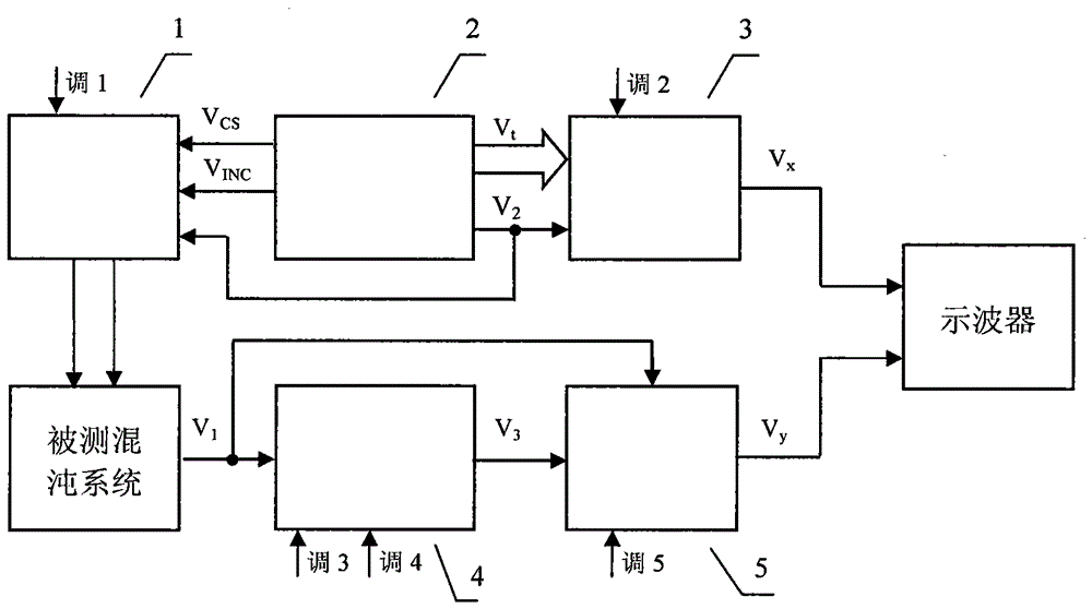
[0021] Such as figure 1 As shown, a CPLD-based oscilloscope display circuit for observing the bifurcation of a chaotic system includes a controllable resistor network 1, a CPLD signal circuit 2, a parameter signal circuit 3, an acquisition signal position circuit 4 and an acquisition signal circuit 5, and a CPLD signal circuit 2 Connect the controllable resistance network 1 and the parameter signal circuit 3 respectively, and the acquisition signal position circuit 4 is connected to the acquisition signal circuit 5, and the two external terminals of the controllable resistance network 1 are connected to both ends of the resistance to be measured of the chaotic system under test to obtain the signal The position circuit 4 and the acquisition signal circuit 5 simultaneously receive the signal V generated by the chaotic system under test 1 , the parameter signal circuit 3 outputs the signal V sent to the X-axis input terminal of the oscilloscope x , to obtain the signal V output...

Embodiment 2

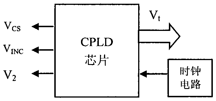
[0029] combine image 3 , introduce the CPLD signal circuit part of the present invention below:

[0030] The purpose of the CPLD signal circuit is to generate three digital signals to control the change of the resistance value in the controllable resistor network, and at the same time generate an 8-bit digital signal V t It is sent to the parameter signal circuit to generate the oscilloscope level signal V that varies with the parameters of the system under test x .

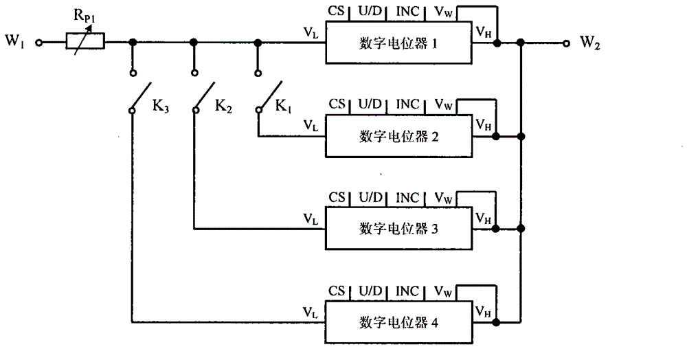
[0031] CPLD signal circuit is composed of CPLD chip and clock circuit. The clock circuit generates a 50MHz clock pulse signal for the CPLD chip to work. The CPLD chip is programmed by Verilog, and then downloaded to the EPM240 chip of the ALTERA Max II series after being compiled by Quartus II, that is, the CPLD chip is an internal circuit formed according to the layout and wiring of the program. The CPLD chip has four output ports, one of which outputs a digital signal V CS ; One of the output terminals ou...

Embodiment 3

[0037] combine Figure 4 , introduce the parameter signal circuit part of the present invention below:

[0038] The purpose of the parameter signal circuit is to generate the signal V that is fed into the X-axis of the oscilloscope x ,See figure 1 and Figure 4 shown.

[0039] The parameter signal circuit is composed of a digital-to-analog conversion circuit and a signal selection circuit. The parameter signal circuit has two input terminals and one output terminal. One input receives the 8-bit sawtooth digital signal V generated by the CPLD signal circuit t , the other input end, receiving CPLD signal circuit to generate 1-bit digital signal V 2 , the output terminal outputs the signal V x .

[0040] The digital-to-analog conversion circuit is composed of a digital-to-analog converter, a first operational amplifier A 1 and reference voltage V R1 consist of. The input terminal of the digital-to-analog converter receives the 8-bit sawtooth digital signal V generated ...


PUM


Abstract

The invention discloses a CPLD-based oscilloscope display circuit for observing chaotic system bifurcations. The CPLD-based oscilloscope display circuit comprises a controllable resistance network circuit, a CPLD signal circuit, a parameter signal circuit, a signal position obtaining circuit and a signal obtaining circuit. The CPLD signal circuit is respectively connected with a controllable resistance network and the parameter signal circuit, the signal position obtaining circuit is connected with the signal obtaining circuit, the two external connection ends of the controllable resistance network are connected to the two ends of a to-be-measured resistor of a measured chaotic system in parallel, the signal position obtaining circuit and the signal obtaining circuit receive signals V1 generated by the measured chaotic system at the same time, the parameter signal circuit outputs signals Vx sent into the input end of an X shaft of an oscilloscope, and the signal obtaining circuit outputs signals Vy sent into the input end of a Y shaft of the oscilloscope. The CPLD-based oscilloscope display circuit is suitable for observing bifurcation diagrams of the chaotic system with changed resistance parameters. The CPLD-based oscilloscope display circuit can be used in on-line monitoring, and can be used for system researching and chaos teaching demonstrating. The CPLD-based oscilloscope display circuit is low in cost, convenient to operate and high in measurement speed.

Description

technical field [0001] The invention relates to an oscilloscope display technology, in particular to a CPLD-based oscilloscope display circuit for observing the bifurcation of a chaotic system. Background technique [0002] A chaotic system is a nonlinear system, and one of its main characteristics is that it is very sensitive to the initial value and system parameters. Any slight change in the system parameters will cause the state of the chaotic system to change, so that it enters a different chaotic state, or exits the chaotic state. The bifurcation diagram is an important tool to understand the state of the chaotic system, especially to observe the state of the system in real time online. At present, there are two attitudes towards chaos: one is to use chaos, such as: chaos is used as an encrypted signal or to detect small signals in secure communication; the other is to suppress chaos, avoid nonlinear systems from entering a chaotic state, and keep the system in a stabl...

Claims


Application Information

Patent Timeline
Patent Type & Authority Patents(China)
IPC IPC(8): G01R13/02
Inventor 陈红杨凯顾书斌孟宇
Owner HEILONGJIANG UNIV
Why Eureka
Try Eureka