Vibration monitor and earthquake vibration monitoring apparatus

A vibration monitoring and monitor technology, applied in the direction of seismic signal receivers, etc., can solve the problems of complex sensor structure, high resonance frequency, high cost, etc., and achieve the effects of high detection accuracy, low resonance frequency, and small elastic coefficient

Inactive Publication Date: 2014-12-03
BEIJING JIAYUE TONGLEJI ELECTRONICS
View PDF10 Cites 5 Cited by
  • Summary
  • Abstract
  • Description
  • Claims
  • Application Information

AI Technical Summary

Problems solved by technology

[0002] In the highly developed modern industry, modern testing technology has become an inevitable development trend towards digitization and informationization, and the front end of the testing system is the sensor, especially the vibration detection. However, the existing vibration monitor, such as the patent US20090195243 The disclosed sensor includes a cantilever arm, a magnet arranged on the cantilever arm, and a GMR detection unit for detecting the vibration signal caused by the magnet. GMR (Giant Magneto Resistive) senses this change and outputs a vibration signal to detect the corresponding vibration signal. Due to the high resonance frequency of the cantilever beam, it is easy to limit and affect the sensitivity of the magnetic sensor. If the cantilever beam is made too thin to If the resonance frequency is lowered, deformation will easily occur, and at the same time, it will inevitably cause distortion and deformation of the cantilever beam, which will bring detection errors, and the above-mentioned sensor has a complex structure, difficult assembly and high cost.

Method used


Image

  • Vibration monitor and earthquake vibration monitoring apparatus
  • Vibration monitor and earthquake vibration monitoring apparatus
  • Vibration monitor and earthquake vibration monitoring apparatus

Examples


Embodiment Construction

[0033] In order to describe the technical content, structural features, achieved goals and effects of the present invention in detail, the following will be described in detail in conjunction with the embodiments and accompanying drawings.

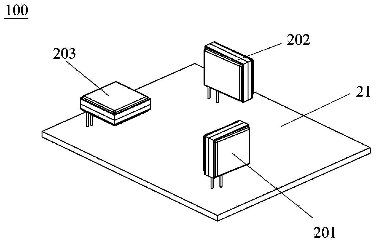
[0034] refer to figure 1 , the present invention discloses an earthquake vibration monitoring device 100 comprising a circuit board 21, an X-axis vibration detection unit 201 installed on the circuit board 21, a Y-axis vibration detection unit 202 and a Z-axis vibration detection unit 203, the X-axis vibration detection unit 203 The axial vibration detection unit 201 , the Y-axis vibration detection unit 202 and the Z-axis vibration detection unit 203 are all vibration monitors 200 and detect vibration signals in the X-axis direction, the Y-axis direction and the Z-axis direction respectively.

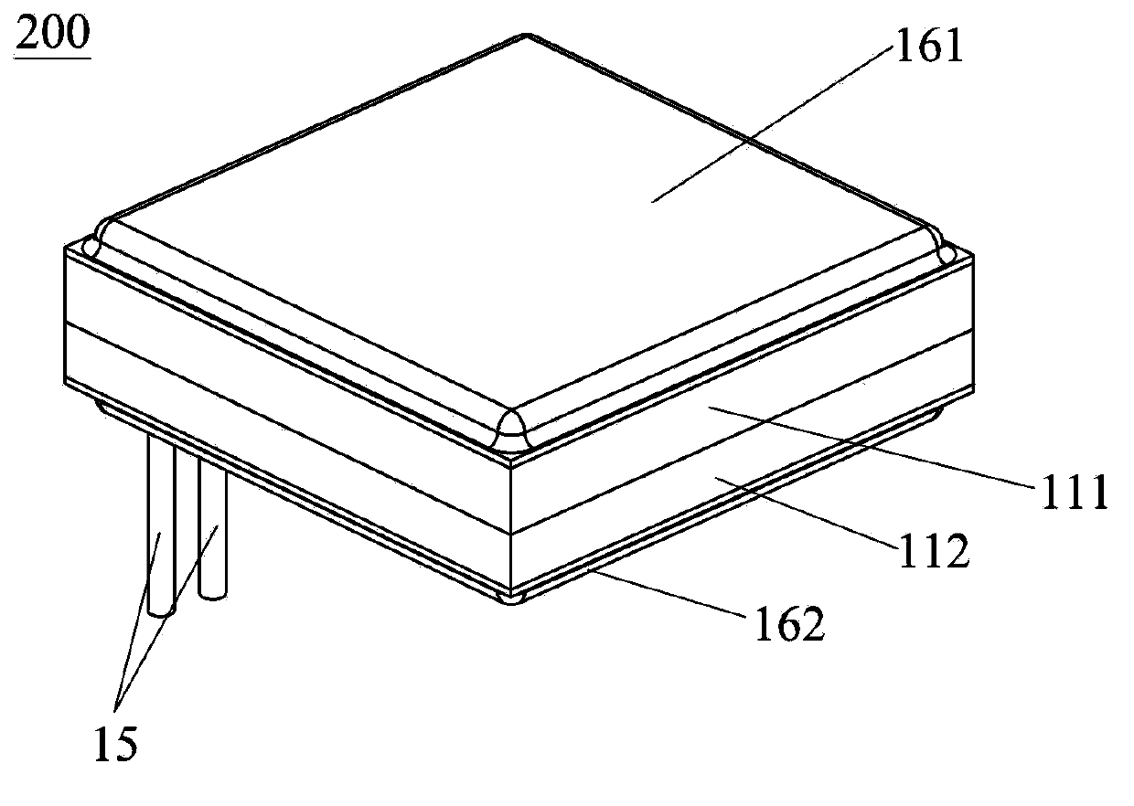
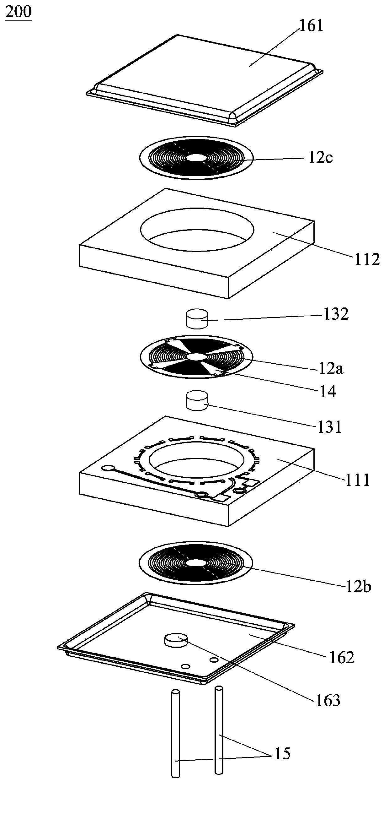
[0035] refer to Figure 2 to Figure 4 , the vibration monitor 200 includes a base 111, a vibration sensing part, a first elastic plate 12a and a ...


PUM


Abstract

The invention discloses an earthquake vibration monitoring apparatus comprising a vibration monitor including a base body, an elastic plate, a vibration sensing portion, and an oscillator installed at the elastic plate. The circumferential edge of the elastic plate is supported on the base body. The base body has a hollow structure and provides a motion space for the elastic plate. When being vibrated, the elastic plate moves along the direction perpendicular to the elastic plate and drives the oscillator to move; and the vibration sensing portion senses the movement of the elastic plate to generate a vibration signal. Compared with the prior art, the apparatus has the following beneficial effects: the elastic plate vibrates along the axial direction; the resonant frequency is low; the elastic coefficient is low; the vibration induction sensitivity is high; the detection sensitivity is high; the structure is simple; and the cost is low. Therefore, the vibration monitor can sense the tiniest vibration by the elastic plate, so that the detection precision is high.

Description

technical field [0001] The invention belongs to the technical field of micro-nano electronics, and in particular relates to a vibration monitor for monitoring earthquake vibration signals and an earthquake vibration monitoring device. Background technique [0002] In the highly developed modern industry, modern testing technology has become an inevitable development trend towards digitization and informationization, and the front end of the testing system is the sensor, especially the vibration detection. However, the existing vibration monitor, such as the patent US20090195243 The disclosed sensor includes a cantilever arm, a magnet arranged on the cantilever arm, and a GMR detection unit for detecting the vibration signal caused by the magnet. GMR (Giant Magneto Resistive) senses this change and outputs a vibration signal to detect the corresponding vibration signal. Due to the high resonance frequency of the cantilever beam, it is easy to limit and affect the sensitivity ...

Claims


Application Information

Patent Timeline
Patent Type & Authority Applications(China)
IPC IPC(8): G01V1/18
Inventor 刘乐杰彭春雷
Owner BEIJING JIAYUE TONGLEJI ELECTRONICS
Why Eureka
Try Eureka