
Combined low voltage control switchgear

A low-voltage control, combined technology, applied in the board/panel/desk, busbar/circuit arrangement, substation/distribution enclosure, etc. of the substation/switchgear, etc. Expansion of the fault range and other problems, to achieve the effect of stable connection and disconnection, personal safety, and convenient operation

Inactive Publication Date: 2016-08-24
沈阳天维电气设备制造有限公司
View PDF5 Cites 1 Cited by
  • Summary
  • Abstract
  • Description
  • Claims
  • Application Information

AI Technical Summary

Problems solved by technology

[0003] The existing low-voltage power distribution cabinet is a frame-type box structure. Various components in the cabinet share a box. When a sub-circuit fails, other components in the same box will be affected by it. If the circuit needs to be replaced, it needs to be replaced. It can be overhauled only after the main circuit switch is disconnected, which will expand the fault range
How to divide the circuit to seal the cavity and how to avoid affecting other adjacent circuits in the event of an accident have always been the difficulties in the design of the cabinet; when a circuit in the cabinet needs to be overhauled in the traditional cabinet, the main switch must be disconnected before maintenance. As a result, the power supply of adjacent circuits in the same cabinet is affected. How to realize the maintenance of sub-circuits without affecting the adjacent circuits is a difficult point in cabinet design

Method used


Image

  • Combined low voltage control switchgear
  • Combined low voltage control switchgear
  • Combined low voltage control switchgear

Examples


Embodiment Construction

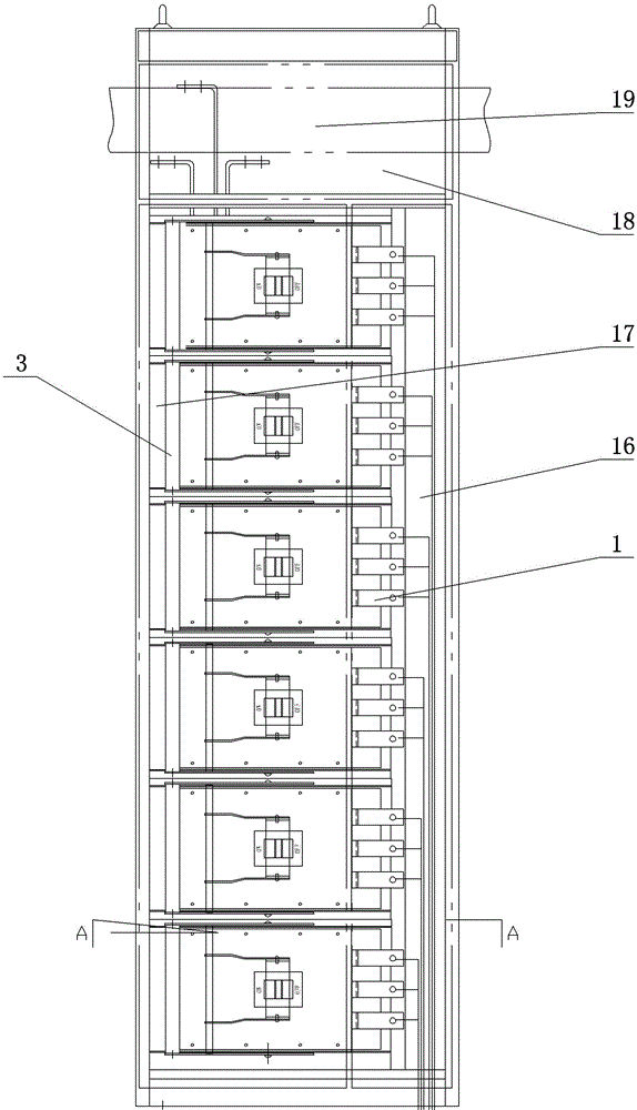
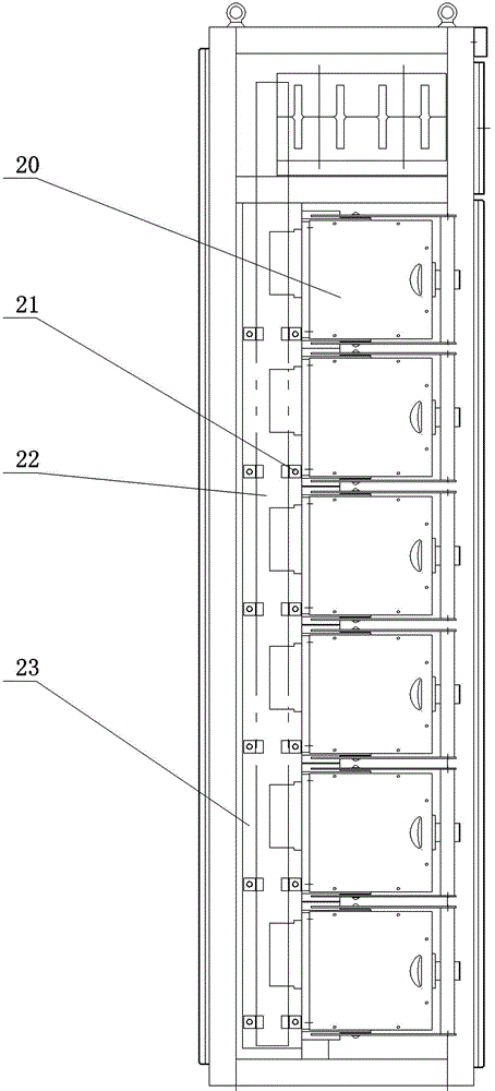
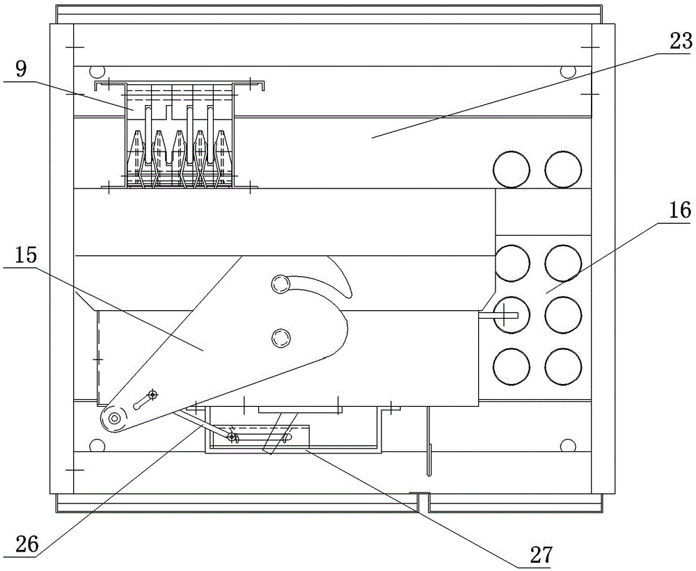
[0032] As shown in the figure, the present invention includes a cabinet body. The upper end of the cabinet body is the main busbar room, the front part of the cabinet body is the switch room, the side part of the cabinet body is the cable room, and the rear part of the cabinet body is the auxiliary busbar room. The vertical auxiliary busbar of the main busbar is connected with the horizontal main busbar of the main busbar room; the switch room includes multiple switch chambers arranged vertically, each switch chamber includes a fixed bracket box, and the front side of the fixed bracket box is a movable bracket The fixed bracket box is fixed with a vertical busbar with a plug at the front end. The vertical busbar is connected to the auxiliary busbar. The plug corresponding to the vertical busbar on the movable bracket box is provided with a plug-in chuck. It is connected to the input end of the circuit breaker through the inner drain bar, and the circuit breaker is arranged on t...


PUM


Abstract

A combined low-voltage control switchgear belongs to the technical field of low-voltage control switchgear, and in particular relates to a combined low-voltage control switchgear. The invention provides a combined low-voltage control switch cabinet with safe use, convenient operation and convenient maintenance. The present invention adopts the following technical scheme. The present invention includes a cabinet body. The upper end of the cabinet body is the main busbar room, the front part of the cabinet body is the switch room, the side part of the cabinet body is the cable room, and the rear part of the cabinet body is the auxiliary busbar room. The vertical auxiliary busbars in the busbar room are connected to the horizontal main busbars in the main busbar room; the switch room includes multiple switch chambers arranged vertically, each switch chamber includes a fixed bracket box, and the front side of the fixed bracket box is a movable The fixed bracket box is fixed with a vertical busbar with a plug at the front end, the vertical busbar is connected to the auxiliary busbar, and the plug corresponding to the vertical busbar on the movable bracket box is provided with a plug chuck. The clip is connected to the input terminal of the circuit breaker through the inner drain bar.

Description

technical field [0001] The invention belongs to the technical field of low-voltage control switch devices, and in particular relates to a combined low-voltage control switch cabinet. Background technique [0002] Based on the continuous development of the power industry, higher requirements are put forward for the power distribution system. High protection, uninterrupted power supply, independent cavity formation of each sub-circuit, and minimized circuit fault range have become higher requirements for products in the market. [0003] The existing low-voltage power distribution cabinet is a frame-type box structure. Various components in the cabinet share a box. When a sub-circuit fails, other components in the same box will be affected by it. If the circuit needs to be replaced, it needs to be replaced. It can be overhauled only after the main circuit switch is disconnected, which will expand the scope of the fault. How to divide the circuit to seal the cavity and how to a...

Claims


Application Information

Patent Timeline
Patent Type & Authority Patents(China)
IPC IPC(8): H02B1/30H02B1/20H02B1/04
Inventor 王瑞林王越龙张振东
Owner 沈阳天维电气设备制造有限公司
Learn More