
Battery charge and discharge control system and method

A charge and discharge control, battery technology, applied in battery circuit devices, current collectors, electric vehicles, etc., can solve problems such as battery scrapping

Active Publication Date: 2017-01-04
奇瑞新能源汽车股份有限公司
View PDF6 Cites 0 Cited by
  • Summary
  • Abstract
  • Description
  • Claims
  • Application Information

AI Technical Summary

Problems solved by technology

[0003] In order to overcome the deficiencies of the prior art, the present invention provides a battery charging and discharging control system based on bidirectional inverter technology. By adding an AC-DC converter between the rectifier and the load, it solves the problem that a large number of batteries are easily generated in the centralized management mode of the industrial computer. For the problem of scrapping, apply current feedback technology, the input current tracks the input voltage, so that the total harmonic content THD of the input current is less than 5%, and the power factor can be improved to 0.99 or higher

Method used


Image

  • Battery charge and discharge control system and method
  • Battery charge and discharge control system and method
  • Battery charge and discharge control system and method

Examples


Embodiment Construction

[0012] Referring to the accompanying drawings, through the description of the embodiments, the specific embodiments of the present invention include the shape, structure, mutual position and connection relationship of each part, the function and working principle of each part, and the manufacturing process of the various components involved. And the method of operation and use, etc., are described in further detail to help those skilled in the art have a more complete, accurate and in-depth understanding of the inventive concepts and technical solutions of the present invention.

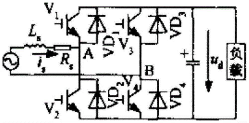
[0013] Such as figure 1 As shown, when u s >0, by V 2 ,VD 4 ,VD 1 , L s and V 3 ,VD 1 ,VD 4 , L s Two boost chopper circuits are formed respectively. to contain V 2 The boost chopper circuit as an example, when V 2 When on, u s through V 2 ,VD 4 to L s stored energy, when V 2 In shutdown, L s The stored energy passes through VD 1 , VD 4 Charge the capacitor C on the DC side. by V ...


PUM


Abstract

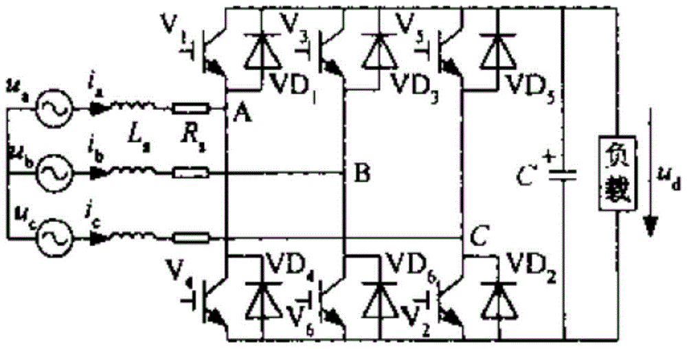
The invention relates to a charging and discharging control system and method for a storage battery, which includes a rectifier and a load. A capacitor C is connected in parallel at both ends of the load. The rectifier is connected in series with an inductance L and a resistor Rs. An AC-DC converter is added between the rectifier and the load. ‑DC converter is a half bridge full bridge circuit composed of insulated gate bipolar transistor V and diode VD connected in parallel. Each two-phase circuit of the full bridge circuit includes an insulated gate bipolar transistor V, diode VD, diode VD and inductor Ls Two boost chopper circuits are formed. The DC side voltage of the system is controlled by the IGBT V duty cycle. The present invention adds a DC-DC converter between the control rectifier and the load, applies current feedback technology, and the input current tracks the input voltage, so that the total harmonic content THD of the input current is less than 5%, and the power factor can be increased to 0.99 or higher. This scheme becomes active power factor correction due to the application of active devices.

Description

technical field [0001] The invention relates to a storage battery charging and discharging control system based on bidirectional inverter technology, which belongs to the technical field of vehicle product testing. Background technique [0002] The current battery charging and discharging system uses industrial computer as the control hub, which is a centralized management method. Once the industrial computer fails, a large number of batteries controlled by it will be scrapped, which will bring great economic losses to the manufacturer. Contents of the invention [0003] In order to overcome the deficiencies of the prior art, the present invention provides a battery charging and discharging control system based on bidirectional inverter technology. By adding an AC-DC converter between the rectifier and the load, it solves the problem that a large number of batteries are easily generated in the centralized management mode of the industrial computer. For the problem of scrap...

Claims


Application Information

Patent Timeline
Patent Type & Authority Patents(China)
IPC IPC(8): H02M7/797H02M1/42H02J7/00H02J7/10
Inventor 赵成飞曹学礼杨朋朋刘燕迪
Owner 奇瑞新能源汽车股份有限公司
Learn More