Efficient multifunctional tool for finish machining of piston

A multi-functional, piston technology, applied in the direction of pistons, manufacturing tools, metal processing equipment, etc., to achieve efficient multi-functional, eliminate shear stress, and ensure stability

Inactive Publication Date: 2014-12-10
安庆雅德帝伯活塞有限公司
View PDF8 Cites 5 Cited by
  • Summary
  • Abstract
  • Description
  • Claims
  • Application Information

AI Technical Summary

Problems solved by technology

[0003]When machining piston snap ring grooves in ordinary production lines (production lines with a cycle time of 38s), the feed speed is F550, and the coaxiality of the snap ring grooves processed at this time is the best, reaching 0.10mm or less (technical requirement is less than 0.2mm), but in the fast line (production line with cycle 33s) snap ring groove processing, the feed speed must be doubled to meet the cycle 33s, but the coaxiality of the snap ring groove obtained is sometimes biased The upper limit even exceeds the specification. This is because the machining feed speed is too fast, and the swaying deviation of the tool rod reaches 0.10mm. At the same time, the greater the shear stress on the tool rod, and on the same side, the greater the resistance to the tool rod, and it is easy to cause the tool to collapse. lack
In addition, an additional tool is required to process the internal chamfering of the piston pin hole. The tool change in the tool magazine and the separate internal chamfering process will affect at least 10 seconds, which will become a bottleneck process and affect the overall processing cycle.

Method used


Image

  • Efficient multifunctional tool for finish machining of piston
  • Efficient multifunctional tool for finish machining of piston
  • Efficient multifunctional tool for finish machining of piston

Examples


Embodiment Construction

[0021] A preferred embodiment of the present invention will be described in detail below with reference to the accompanying drawings.

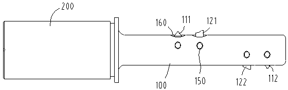
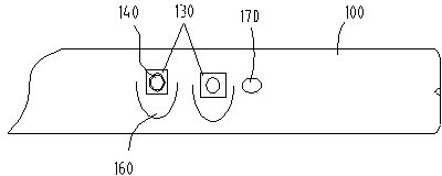
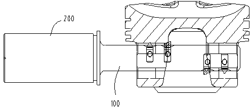
[0022] Such as figure 1 and 3 As shown, the high-efficiency multifunctional tool for piston finishing of the present invention includes a cutter bar 100 and a tool handle 200 connected in sequence, wherein the tool handle is connected with a rotating device to drive the tool bar to rotate synchronously to complete the work. The first snap ring groove cutter 111, the first inner chamfering cutter 121, the second inner chamfering cutter 122 and the second snap ring groove cutter 112 are arranged in sequence along the axial cylindrical side on the said cutter bar 100, wherein the first snap ring groove cutter The ring groove cutter and the first inner chamfering cutter are located on the same side, and the second inner chamfering cutter and the second snap ring groove cutter are located on the same side. Size design. The first snap ring groov...


PUM


Abstract

The invention provides an efficient multifunctional tool for finish machining of a piston. The efficient multifunctional tool comprises a shank and a toolbar connected in order. The axial cylindrical side of the toolbar is provided with a pair of snap ring groove blades used for machining snap ring grooves of the piston and a pair of inner chamfer blades used for machining an inner chamfer of the piston. The inner chamfer blades are disposed on the toolbar between the snap ring groove blades. The snap ring groove blades and the inner chamfer blades are both arranged on opposite sides of the toolbar. The efficient multifunctional tool has the advantages tangential force that blade edges bear when snap ring grooves of the piston and the inner chamber of a pinhole are under machining can be eliminated, the toolbar shakes less during machining accordingly, machining stability is improved, coaxiality of the snap ring grooves is improved, product quality stability is guaranteed, snap ring grooves and the inner chamfer of the pinhole are machined at the same time, machining cycle is shortened, and high efficiency and multifunctionality are achieved.

Description

technical field [0001] The invention relates to the technical field of piston finishing, in particular to a multifunctional cutter used for finishing the internal chamfering of piston snap ring grooves and pin holes. [0002] Background technique [0003] When processing piston snap ring grooves in ordinary production lines (production lines with a cycle time of 38s), the feed speed is F550. At this time, the coaxiality of the snap ring grooves processed is the best, reaching below 0.10mm (the technical requirement is below 0.2mm), but in the fast line (Production line with cycle 33s) When processing the snap ring groove, the feed speed must be doubled to meet the cycle 33s, but the coaxiality of the snap ring groove obtained sometimes deviates from the upper limit or even exceeds the specification, because the processing feed speed is too fast, The swaying deviation of the tool rod reaches 0.10mm. At the same time, the greater the shear stress on the tool rod, and on the ...

Claims


Application Information

Patent Timeline
Patent Type & Authority Applications(China)
IPC IPC(8): B23B27/00
CPCB23B27/00B23B2200/3609B23B2215/245
Inventor 张莉莉沈银龙汪宝俊王向峰
Owner 安庆雅德帝伯活塞有限公司
Why Eureka
Try Eureka