Rearward pull clamping type lathe fixture for processing of inner hole and end faces of thin-walled part

A technology of thin-walled parts and vehicle fixtures, which is applied in the direction of metal processing machinery parts, manufacturing tools, metal processing equipment, etc., can solve the problems that affect the process processing, cannot be close to the positioning surface, and the clamping force is large, so as to facilitate mass production , It is not easy to deform the workpiece, and the effect of simple structure

Active Publication Date: 2014-12-10
JIANGSU SAIC AUTOMOBILE SYNCHRONIZER WORKS
View PDF6 Cites 9 Cited by
  • Summary
  • Abstract
  • Description
  • Claims
  • Application Information

AI Technical Summary

Problems solved by technology

First of all, gear sleeves are usually thin-walled parts, and the three jaws can only clamp the workpiece at three places in one circle. When the three claws are loosened, the inner hole is easy to become a triangle, and the clamping force driven by the hydraulic pressure is too large, which makes the parts deform more seriously, affects the subsequent process processing, and is not conducive to product quality control; second, the three claws Clamping and unclamping are slow, which is not conducive to mass production; third, when the clamping part is against the positioning surface, it is necessary to hold the workpiece close to the positioning surface and wait for the three-jaw clamping before it can be removed. During this process, the workpiece is easy to It is moved outward by the clamping force of the three jaws, so it cannot be close to the positioning surface, and it is easily affected by human factors. It cannot ensure that the positioning of the parts is close to the three-jaw chuck, and the reliability is not good; fourth, it is inconvenient to adjust the machine tool. Re-turn the claws, after several times of claws, the claws become thinner and scrapped prematurely

Method used


Image

  • Rearward pull clamping type lathe fixture for processing of inner hole and end faces of thin-walled part
  • Rearward pull clamping type lathe fixture for processing of inner hole and end faces of thin-walled part

Examples


Embodiment Construction

[0023] The present invention will be further described below in conjunction with the accompanying drawings and specific embodiments.

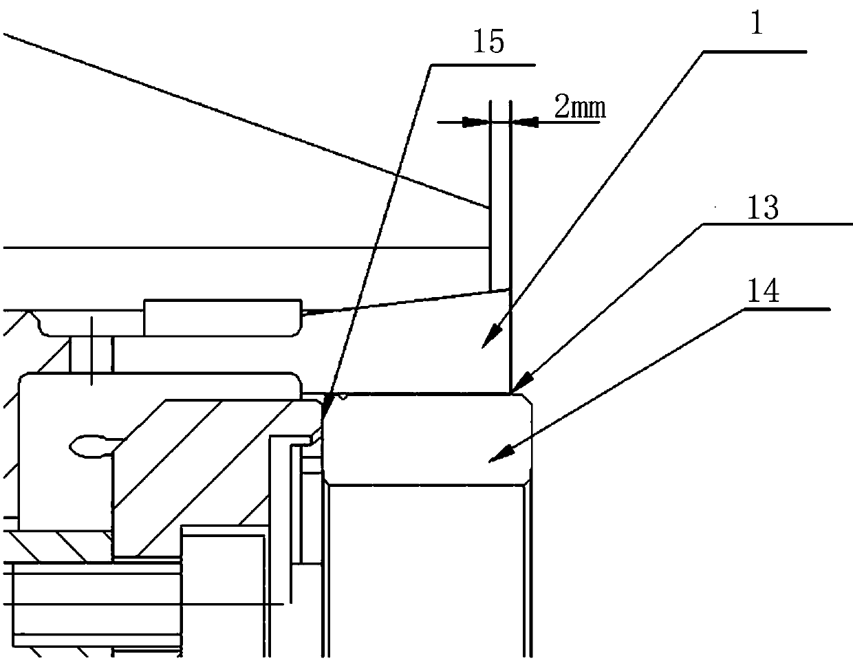
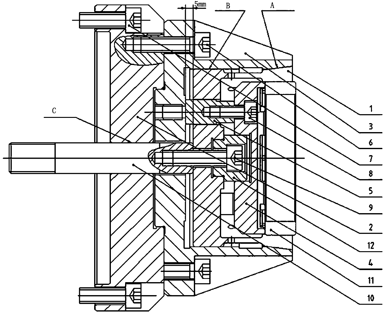
[0024] according to figure 1 with figure 2 , a back-tight clamp for the inner hole and end face of a thin-walled part, including a jacket 1, a connecting plate 2, a cylindrical base 3 (a cylindrical disc base), a positioning seat 4, a connecting rod 5, and a pull rod 10. Calibration piece 11, positioning sleeve 12, and socket head cap screws 6, 7, 8, 9 for connection. The cylindrical base 3 is close to the end face (i.e. figure 2 The inclined surface connected with the jacket 1) has a 7°30’ taper in the inner diameter, which matches with the 7°30’ taper in the outer diameter of the jacket 1 (that is, the outer circle of the jacket). One end of the tie rod 10 is connected with the lathe oil cylinder, and the other end is connected with the jacket 1 through the hexagon socket cap screw 9 . One end of the positioning sleeve 12 is slidingly m...


PUM


Abstract

The invention discloses a rearward pull clamping type lathe fixture for processing of an inner hole and end faces of a thin-walled part. The rearward pull clamping type lathe fixture comprises a tubular base; one end face, which is tapered, of the tubular base is as tapered as the outside of one end of an elastic collet; the tubular base which is a disc base is fixed while the elastic collet is slidable; the inside of the elastic collet clamps the outside of a workpiece, and a gap remains between the inside of the elastic collet and the outside of the workpiece so as to favor clamping of the workpiece. When a cylinder drives a pull rod to pull the elastic collet to slide rearward, the elastic collet contracts to clamp the workpiece; while the elastic collet moves rearward and gradually clamps the workpiece, the workpiece is driven to move rearward to tightly attach to a positioning seat. A positioning sleeve is arranged among the positioning seat of the fixture, the elastic collet and the pull rod so that coaxiality of the positioning seat, the elastic collet and the pull rod is guaranteed. The rearward pull clamping type lathe fixture has the advantages that deformation of the thin-walled part can be effectively reduced, clamping is facilitated, positioning is reliable, and batch production of parts is facilitated.

Description

technical field [0001] The invention belongs to the field of lathe fixtures, in particular to a back-tightening type lathe fixture for processing the inner hole and end face of a thin-walled part. [0002] Background technique [0003] In the gear sleeve processing process, for the special structure of some parts, the process needs to process the inner spline hole of the gear sleeve. The end face angle requirements are high, and the end face of the gear sleeve is required. In the above situation, the usual clamping method is to use a three-jaw chuck to clamp the outer circle of the part, and one end of the workpiece is close to the positioning surface. Using a three-jaw chuck is simple and efficient, but there are several problems. First of all, gear sleeves are usually thin-walled parts, and the three jaws can only clamp the workpiece at three places in one circle. When the three claws are loosened, the inner hole is easy to become a triangle, and the clamping force dri...

Claims


Application Information

Patent Timeline
Patent Type & Authority Applications(China)
IPC IPC(8): B23Q3/12
CPCB23Q3/12
Inventor 朱海明顾晓勇祝金
Owner JIANGSU SAIC AUTOMOBILE SYNCHRONIZER WORKS
Why Eureka
Try Eureka