Special peed change mechanism for numerical control machine tool

A technology of speed change mechanism and numerical control machine tool, which is applied to metal processing mechanical parts, drive devices, metal processing equipment, etc., can solve the problems of inconvenient work, low speed change efficiency and long shift time of numerical control machine tools, so as to achieve economical manufacturing cost, The effect of compact structure and convenient maintenance

Inactive Publication Date: 2014-12-10
NANTONG JINGDING CNC EQUIP
View PDF0 Cites 3 Cited by
  • Summary
  • Abstract
  • Description
  • Claims
  • Application Information

AI Technical Summary

Problems solved by technology

At present, the gear transmission mechanism of CNC machine tools basically has two forms: manual operation mechanism and hydraulic transmission mechanism. Among them, the structure of manual operation mechanism is relatively simple and primitive, but it is inconvenient to work on the CNC machine tool, and it cannot be fully automated during the working process of the machine tool. When shifting, the operator needs to stop the main rotation of the machine tool. Manually shifting gears, the shifting efficiency is low; the hydraulic shifting mechanism uses hydraulic cylinders or pistons to push the sliding gears to move to achieve shifting. It is currently the most widely used shifting on CNC machine tools. The mechanism adopts the method of rotating at low speed first and then meshing when shifting gears, but its disadvantage is that it needs to run at low speed first to avoid the top teeth, resulting in long shifting time, low efficiency, and the need for complex hydraulic system support, which increases product costs.

Method used


Image

  • Special peed change mechanism for numerical control machine tool
  • Special peed change mechanism for numerical control machine tool

Examples


Embodiment 1

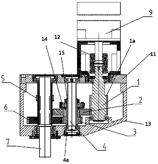
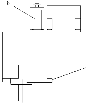
[0018] The present invention comprises driving device 9, shift device 8 and speed change device 11, as figure 1 , figure 2 As shown, the structure of the speed change device 11 is as follows: including a housing 13, a drive shaft 1, a shift shaft 4 and a driven shaft 7;

[0019] The housing 13 is a rectangular cavity with a hypotenuse in the lower right corner;

[0020] The specific positional relationship between the driving shaft 1, the shift shaft 4 and the driven shaft 7 and the housing 13 is as follows: the two ends of the shoulders of the driving shaft 1, the shift shaft 4 and the driven shaft 7 pass through the bearings respectively according to the drive shaft 1, The shifting shaft 4 and the driven shaft 7 are arranged in sequence from right to left in the Y-axis direction inside the cavity of the housing 13, and the shoulders of the driving shaft 1 and the shifting shaft 4 protrude from the upper surface of the housing 13 , the shoulder of the driven shaft 7 protru...


PUM


Abstract

The invention discloses a special speed change mechanism for a numerical control machine tool. The special speed change mechanism comprises a driving device, a gear shifting device and a speed change device. An output shaft of the driving device is connected with an input shaft of the speed change device. The gear shifting device is connected to the speed change device through a shaft. The driving device of the mechanism can achieve interconversion of two rotating speed ranges and torque through gear shifting in a rated speed and rated torque state, and therefore working efficiency is improved. In the mechanism, the driving device is connected with the input shaft of the speed change device through a coupler, the torque of the driving device can be transmitted to the speed change device to the maximum degree, and the coaxiality of the driving device and the speed change device can be adjusted through the coupler. A gear shifting hydraulic oil cylinder or a gear shifting air pressure lever is adopted in the gear shifting device of the mechanism, the proven technique is adopted in the gear shifting device, it can be guaranteed that enough pressure is provided, and both maintenance and preservation at the later period are very convenient and quick. The mechanism is compact in structure and low in manufacturing cost and difficulty brought for an operator.

Description

technical field [0001] The invention relates to numerical control equipment, in particular to a speed change mechanism dedicated to numerical control machine tools. Background technique [0002] CNC machine tool is the abbreviation of numerical control machine tool, which is an automatic machine tool equipped with a program control system. The control system can logically process programs with control codes or other symbolic instructions, decode them, express them in coded numbers, and input them into the numerical control device through the information carrier. After calculation and processing, various control signals are sent by the numerical control device to control the movement of the machine tool, and the parts are automatically processed according to the shape and size required by the drawing. CNC machine tools solve complex, precise, small-batch, and multi-variety parts processing problems. It is a flexible, high-efficiency automatic machine tool that represents the...

Claims


Application Information

Patent Timeline
Patent Type & Authority Applications(China)
IPC IPC(8): B23Q5/12
CPCB23Q5/12
Inventor 孙美华杨雷刘永晨
Owner NANTONG JINGDING CNC EQUIP
Why Eureka
Try Eureka