Lifting structure applicable to high-speed printing system of bubble cap machine

A technology of lifting structure and high-speed printing, which is applied in the field of lifting structure, can solve the problems that the high-speed printing system of the blister machine cannot achieve accurate lifting accuracy, high installation and maintenance requirements, and large transmission power, and achieve stable lifting transmission and high transmission power , Noise and impact resistance

Inactive Publication Date: 2014-12-10
HEFEI AIRWREN AUTOMATIC EQUIP CO LTD
View PDF2 Cites 3 Cited by
  • Summary
  • Abstract
  • Description
  • Claims
  • Application Information

AI Technical Summary

Problems solved by technology

[0002] The lifting structure of the known high-speed printing system of the blister machine adopts a chain drive lifting structure. Compared with the gear drive, it can transmit motion and power when the centers of the two axes are far apart, and can operate at low speeds, heavy loads and high temperatures. Compared with the synchronous belt and wheel transmission, it can ensure the average transmission ratio, the transmission power is large, and the force acting on the shaft and bearing is small, and the transmission efficiency is high. Generally, it can reach 0.95~0.97, but after the hinge of the chain is worn out, the pitch becomes larger and it is easy to cause shedding. The lifting accuracy of the printing system, in order to solve this disadvantage, the present invention is specially developed for this

Method used


Image

  • Lifting structure applicable to high-speed printing system of bubble cap machine

Examples


Embodiment Construction

[0015] The present invention is described in detail below in conjunction with accompanying drawing and specific embodiment:

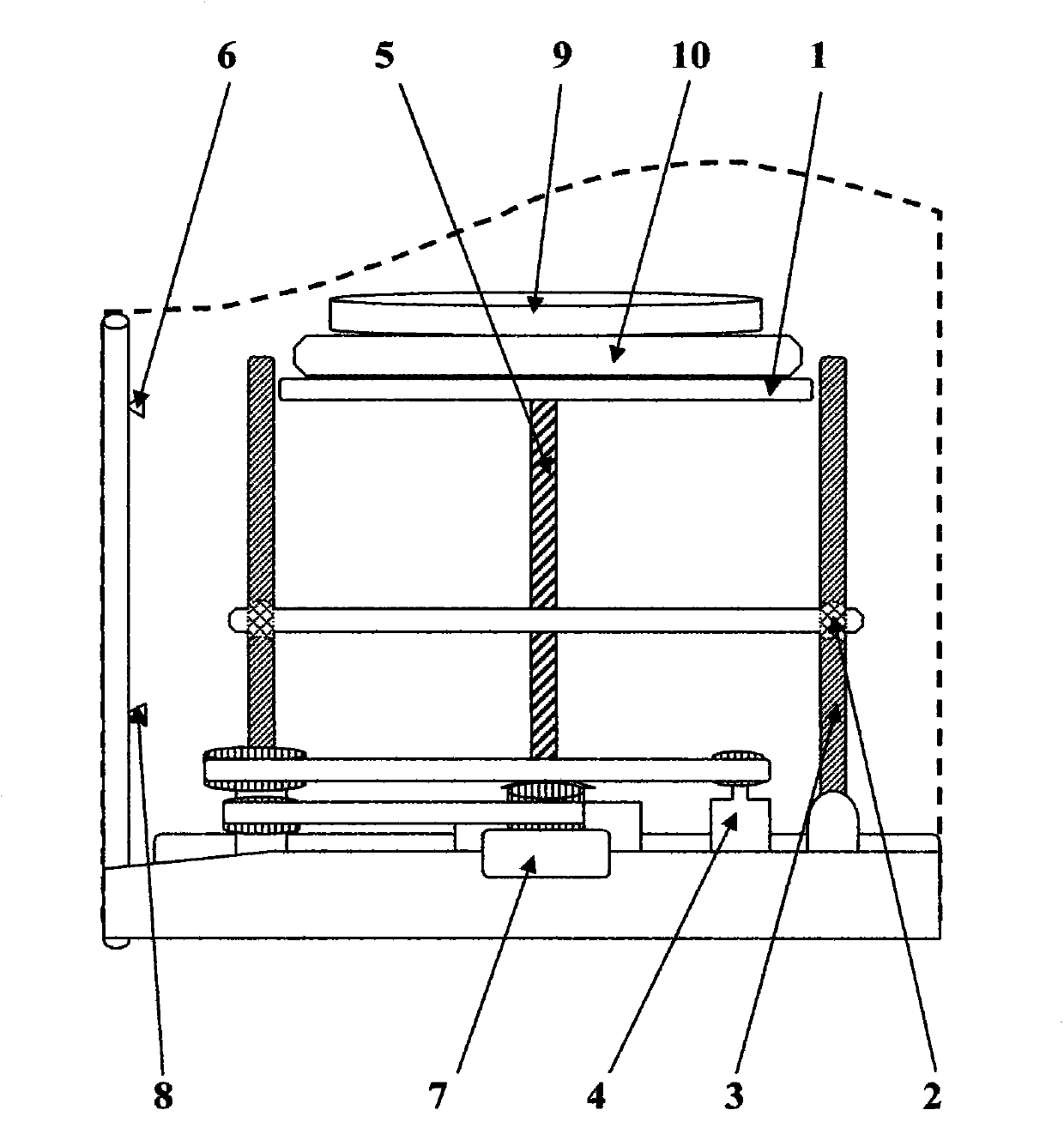
[0016] figure 1 A lifting structure suitable for the high-speed printing system of a blister machine is shown, which has a lifting structure, a lifting drive servo main motor 7 arranged on the left side of the lifting structure, and a lifting rod auxiliary motor 4 for controlling the position of the lifting structure; the lifting structure It is composed of load table 1, sliding tube 2 and lifting auxiliary screw 3. The sliding tube 2 is fixedly arranged between the loading table 1 and lifting auxiliary screw 3 in the shape of "H". The lifting main screw rod 5 of lifting, this lifting main screw rod 5 is connected with lifting drive servo main motor 7;

[0017] The lifting drive servo main motor 7 is linked with the lifting rod auxiliary motor 4 through the synchronous wheel and the synchronous wheel belt. The lifting main screw 5 and the lifting auxil...


PUM


Abstract

The invention discloses a lifting structure applicable to a high-speed printing system of a bubble cap machine. The lifting structure is characterized by comprising a lifting driving servo main motor at the left side of a lifting structure body and a lifting-rod auxiliary motor for controlling the position of the lifting structure body, and the lifting structure body comprises a weight bearing platform, sliding pipes and lifting auxiliary screws, wherein the sliding pipes are fixedly arranged between the weight bearing platform and the lifting auxiliary screws in an H shape; a lifting main screw for controlling the lifting of the left and right sliding pipes is arranged at the middle of the horizontal plane of the left sliding pipe and the right sliding pipe, and is connected with the lifting driving servo main motor; the lifting driving servo main motor and the lifting-rod auxiliary motor are linked with the lifting main screw and the lifting auxiliary screws by synchronous wheels and a synchronous wheel belt to commonly act on the weight bearing platform to drive the weight bearing platform to go up and down; the upper end and the lower end of a frame wall rod at the left side of one lifting auxiliary screw are provided with a front limiter and a rear limiter from top to bottom. The lifting structure disclosed by the invention has the advantages that the lifting transmission is smooth, the transferred power is large, the transmission efficiency is high, the heat resistance is good, lifting transmission noise is low, the impact resistance is achieved, the electrical conductivity is good, the flexural property is good and the like.

Description

technical field [0001] The invention relates to a lifting structure, in particular to a lifting structure suitable for a high-speed printing system of a blister machine. Background technique [0002] The lifting structure of the known high-speed printing system of the blister machine adopts a chain drive lifting structure. Compared with the gear drive, it can transmit motion and power when the centers of the two axes are far apart, and can operate at low speeds, heavy loads and high temperatures. Compared with the synchronous belt and wheel transmission, it can ensure the average transmission ratio, the transmission power is large, and the force acting on the shaft and bearing is small, and the transmission efficiency is high. Generally, it can reach 0.95~0.97, but after the hinge of the chain is worn out, the pitch becomes larger and it is easy to cause shedding. The lifting accuracy of the printing system is accurate. In order to solve this disadvantage, the present inven...

Claims


Application Information

Patent Timeline
Patent Type & Authority Applications(China)
IPC IPC(8): B29C67/00
Inventor 龙梅
Owner HEFEI AIRWREN AUTOMATIC EQUIP CO LTD
Why Eureka
Try Eureka