
An integrated device for aerodynamic deceleration, soft landing and protection of a space probe

A technology of space probes and landing legs, which is applied to the landing device of aerospace vehicles, the system of spacecraft returning to the earth's atmosphere, extraterrestrial vehicles, etc., and can solve the problems of aerodynamic cabin throwing off, dust, and aerodynamic deceleration efficiency of Mars landers Low-level problems, to achieve the effect of small average overload and reduce structural complexity

Inactive Publication Date: 2016-06-08
NORTHWESTERN POLYTECHNICAL UNIV
View PDF8 Cites 0 Cited by
  • Summary
  • Abstract
  • Description
  • Claims
  • Application Information

AI Technical Summary

Problems solved by technology

[0003] Invention patent CN102438906A discloses a "landing device for a space probe and a landing method for a probe equipped with the device". The landing legs can be retracted when landing, but the aerodynamic cabin still needs to be thrown away.
In the prior art, the aerodynamic capsule has been thrown away when it descends to the surface of Mars, and the lander body is directly exposed to the Martian atmosphere; according to existing studies, there is a lot of dust in the Martian atmosphere, especially during Martian storms, when the Martian environment is even harsher. Bare space probes are highly vulnerable to the Martian environment
In summary, the aerodynamic deceleration efficiency of existing Mars landers is low, and the structural utilization rate needs to be improved

Method used


Image

  • An integrated device for aerodynamic deceleration, soft landing and protection of a space probe
  • An integrated device for aerodynamic deceleration, soft landing and protection of a space probe
  • An integrated device for aerodynamic deceleration, soft landing and protection of a space probe

Examples


Embodiment Construction

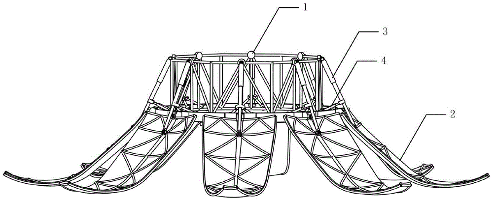
[0024] This embodiment is an integrated device for aerodynamic deceleration, soft landing and protection of a space probe.

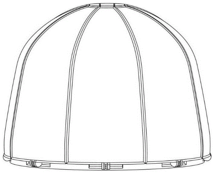
[0025] refer to Figure 1 to Figure 5 , the integrated device of aerodynamic deceleration, soft landing and protection of the space probe in this embodiment,

[0026] Including installation frame 1, petal structure 2, main landing leg 3, auxiliary landing leg 4, hydraulic system, installation frame 1 is a ring-shaped frame structure, installation frame 1 is fixed on the space probe body, petal structure 2 The cloth is installed on the lower end of the installation frame 1 through the rotating shaft, and the main landing legs 3 are evenly distributed along the upper end of the installation frame 1. Connection, the auxiliary landing legs 4 are evenly distributed along the lower end of the installation frame 1, the auxiliary landing legs 4 are fixedly connected to the lower end of the installation frame 1, the other end of the auxiliary landing legs 4 is c...


PUM


Abstract

The invention discloses an integrated device for aerodynamic deceleration, soft landing and protection of a space probe, comprising a mounting frame, a petal structure, a main landing leg, an auxiliary landing leg, and a hydraulic system; the mounting frame is fixed on the space probe body, and the petal structure Installed at the lower end of the installation frame, the main landing leg and the auxiliary landing leg are fixedly connected to the installation frame respectively, the other end of the main landing leg is connected to the central rotating shaft of the petal structure, and the other end of the auxiliary landing leg is connected to the main landing leg. A hydraulic buffer system and a partial hydraulic retractable system are placed in the main landing leg and the auxiliary landing leg to maintain a stable attitude during landing and long-term support after landing; through the device, the function of space probes landing on planets with thin atmospheres can be realized ; At the same time, it can perform soft landing on the surface of the planet; the ratio of the aerodynamic deceleration area of ​​the space probe to the maximum cross-sectional area is large, the aerodynamic deceleration efficiency is high, and the aerodynamic deceleration device does not need to be discarded; it is especially suitable for space probes.

Description

technical field [0001] The invention relates to a spacecraft landing device, in particular to an integrated device for aerodynamic deceleration, soft landing and protection of a space probe. Background technique [0002] Documents "Study on Landing Dynamics Modeling and Simulation of Multi-legged Lunar Exploration Soft Lander" (Nanchang University Master's Degree Thesis, 2008) and "Study on Energy Absorption Characteristics of Leg-type Landing Buffer and Dynamics Simulation of Soft Landing Process" ( Harbin Institute of Technology doctoral dissertation, 2013) described that soft landing landers mostly use leg-type soft landing mechanisms, and the landing legs are evenly distributed around the central axis of the lander. According to the configuration of a single landing leg, the landing leg can be divided into "inverted triangle" and "cantilever beam" landing legs. The buffer is installed in the main pillar and auxiliary pillar of the landing leg. Aluminum honeycomb structur...

Claims


Application Information

Patent Timeline
Patent Type & Authority Patents(China)
IPC IPC(8): B64G1/16B64G1/62
Inventor 胡寒栋曹梦楠时圣波李春娜朱政光戴存喜李可关凌霄
Owner NORTHWESTERN POLYTECHNICAL UNIV
Learn More