Rotating jacking mechanism and AGV comprising same

A technology of jacking mechanism and rotating motor, which is applied in the direction of motor vehicles, lifting frames, lifting devices, etc., can solve the problems of not being able to better meet the needs of flexible handling and loading and unloading of goods, not being able to rotate, and prone to tilting, etc., to achieve a simple structure , small space occupation, good self-locking performance

Active Publication Date: 2014-12-10
湖州上电科电器科学研究有限公司 +3
View PDF8 Cites 55 Cited by
  • Summary
  • Abstract
  • Description
  • Claims
  • Application Information

AI Technical Summary

Problems solved by technology

The lifting mechanism only automatically lifts the driving mechanism of the AGV trolley as a whole, but cannot rotate, which cannot better meet the needs of flexibl

Method used


Image

  • Rotating jacking mechanism and AGV comprising same
  • Rotating jacking mechanism and AGV comprising same
  • Rotating jacking mechanism and AGV comprising same

Examples


Embodiment 1

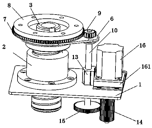
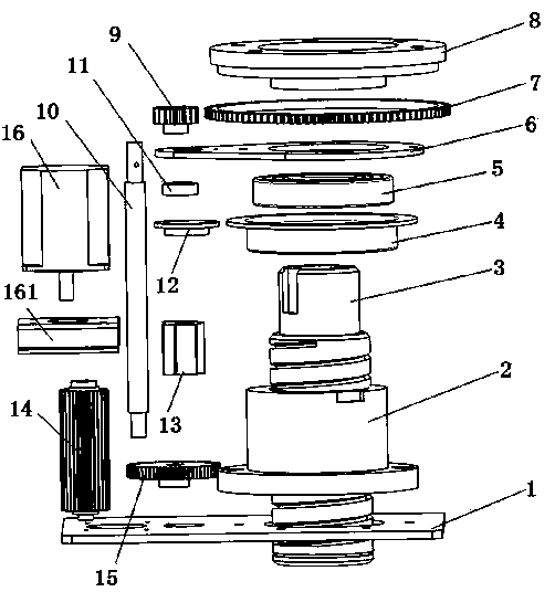
[0029] figure 1 Shown is the three-dimensional structural diagram of the rotary jacking mechanism of the present invention. The rotary jacking mechanism comprises a base fixed plate 1, a rotating motor 16, a transmission assembly, a leading screw 3, a leading screw nut 2, a large bearing bracket 4, a large bearing 5 and a pallet 8. The transmission assembly includes a driving gear 14 , a primary transmission gear 15 , a guide rod 10 , a secondary transmission gear 9 , a gear ring 7 and a linkage plate 6 . The rotating motor 16 is fixed on one side of the upper surface of the base fixing plate 1 by a rotating motor fixing bracket 161. The rotating motor 16 has a built-in motor shaft (not shown in the figure), and the motor shaft is connected to the transmission assembly . The lead screw 3 runs through the base fixing plate 1, and the lead screw 3 is supported on the base fixing plate 1 by the lead screw nut 2, and the transmission assembly is connected with the lead screw 3 a...

Embodiment 2

[0035] Figure 5 Shown is the side sectional view of the AGV trolley comprising the rotary jacking mechanism of the present invention, the AGV trolley includes a walking mechanism consisting of two drive wheels 20 and four universal wheels 21, a vehicle body frame 22, and a vehicle body for the AGV. The battery pack 23, two driving motors 17, two right-angle driving motor reduction boxes 19, one driving motor driver 18, tray support 24, two control panels, navigation device and two are installed on the front of the car and the car respectively, which dolly provides power. Tail infrared sensor. The four universal wheels 21 are positioned at the four corners of the body frame 22, and the two drive wheels 20 are positioned on both sides of the body frame 22, and are installed side by side on the body frame 22 top in turn. The battery pack 23, the rotary jacking mechanism and the driving motor driver 18. The rotary jacking mechanism supports the base fixing plate 1 by a pluralit...


PUM


Abstract

The invention discloses a rotating jacking mechanism and an AGV(Automatic Guided Vehicle) comprising the same and belongs to the field of automatic conveying devices. The rotating jacking mechanism comprises a base fixing plate, a rotation motor, a transmission assembly, a lead screw, a lead screw nut, a large bearing bracket, a large bearing and a hollow tray. The lead screw penetrates through the base fixing plate, and the lead screw is supported on the base fixing plate through the lead screw nut. The large bearing bracket, the large bearing and the tray are sequentially arranged on the lead screw from bottom up. The rotating motor and the transmission assembly are in transmission connection, and the transmission assembly is in transmission connection with the tray and the lead screw. The AGV comprising the rotating jacking mechanism comprises two driving wheels, four universal wheels, a battery pack, two driving motors, a driving motor driver, a vehicle body frame, two control boards, a tray support, two right-angle driving motor reduction boxes, a navigation device and two infrared sensors. According to the invention, the structure is flexible and compact, the dead weight capacity is large, the self-locking performance is good, the lead screw can ascends stably in a rotary manner and the requirements for flexible carrying can be met.

Description

technical field [0001] The invention relates to an automatic conveying device, in particular to a rotary jacking mechanism and an AGV trolley comprising the rotary jacking mechanism. Background technique [0002] Unmanned guided vehicle (AGV for short) refers to a transport vehicle equipped with automatic guidance devices such as electromagnetic or optical, capable of driving along a prescribed path, with safety protection and various transfer functions. This kind of transport vehicle adopts a fully automatic control method instead of manual labor, which saves manpower and is easy to use. It has been widely used in the logistics and transportation industry. [0003] At present, the jacking mechanism used in the AGV trolley is an electric push rod mechanism, an electro-hydraulic push rod mechanism or an X-type double-rod mechanism. Although the electric push rod mechanism and the electro-hydraulic push rod mechanism are simple in structure, strong in carrying capacity, and ...

Claims


Application Information

Patent Timeline
IPC IPC(8): B66F7/14B62D63/04
Inventor 陈云雷曹国强陈建中余渊何瑶瑶杨孟张颖潘吉亮郑群龙夏成
Owner 湖州上电科电器科学研究有限公司
Why Eureka
Try Eureka