A high-power bipolar pulse magnetron sputtering method

A bipolar pulse and magnetron sputtering technology is applied in the field of bipolar pulse magnetron sputtering to achieve the effects of high bonding force, suppressing sparking phenomenon and improving sputtering efficiency

Active Publication Date: 2016-06-29
HARBIN INST OF TECH
View PDF5 Cites 0 Cited by
  • Summary
  • Abstract
  • Description
  • Claims
  • Application Information

AI Technical Summary

Problems solved by technology

[0004] The purpose of the present invention is to provide a high-power bipolar pulse magnetron sputtering method in order to solve the technical problem of sparking caused by the accumulation of charges in the existing high-power single-stage magnetron sputtering

Method used


Image

  • A high-power bipolar pulse magnetron sputtering method
  • A high-power bipolar pulse magnetron sputtering method
  • A high-power bipolar pulse magnetron sputtering method

Examples


specific Embodiment approach 1

[0018] Specific implementation mode one: this implementation mode is a kind of high-power bipolar pulse magnetron sputtering method, is specifically carried out according to the following steps:

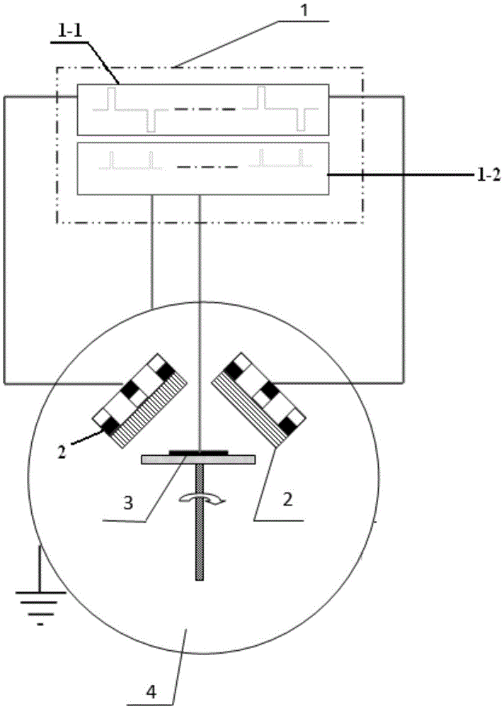
[0019] 1. Installation equipment: fix the cleaned sample on the rotatable sample stage in the vacuum chamber, the cathode of the bias power supply is connected to the sample stage, and the anode of the bias power supply is grounded; install twin targets, and set the target base distance to 3cm to 20cm , set the shortest horizontal distance between the twin targets to 1cm to 20cm; connect the twin targets to the two output terminals of the sputtering power supply respectively; the angle between the twin targets is 10° to 180°;

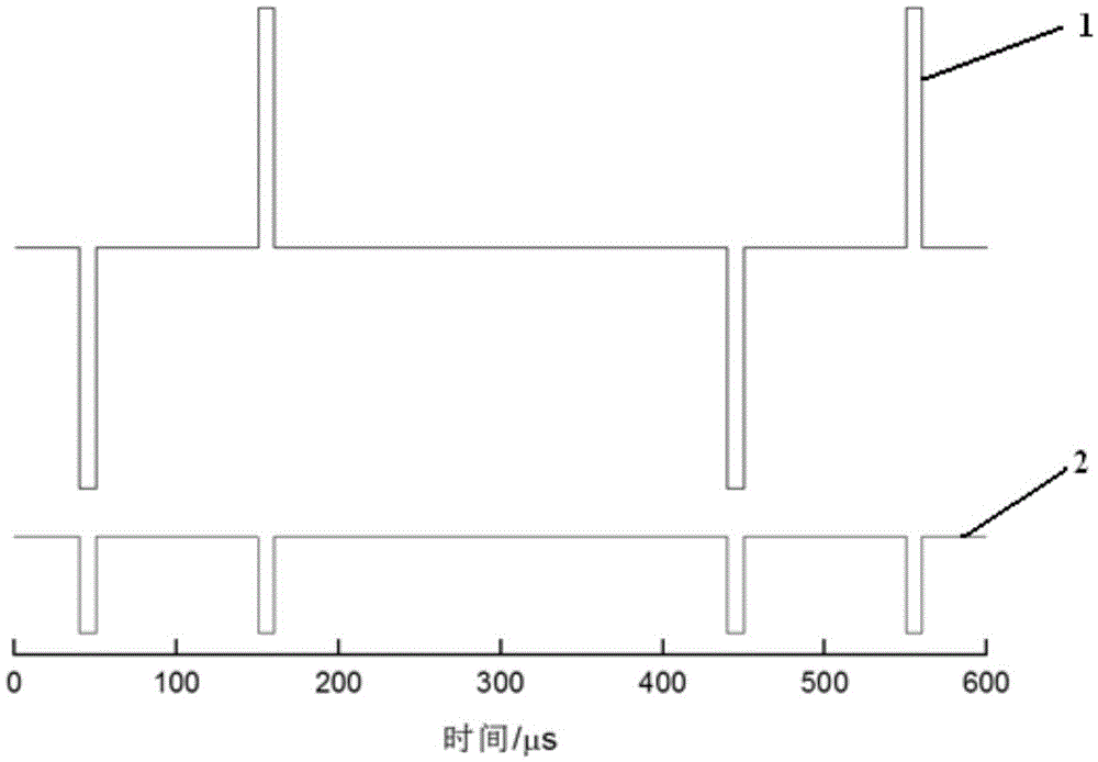
[0020] 2. Set the power supply parameters: set the pulse width of the positive and negative bidirectional pulses of the sputtering power supply to be the same and both are greater than 0ms and less than or equal to 5ms. Set the time interval of the positive and...

specific Embodiment approach 2

[0030] Embodiment 2: This embodiment differs from Embodiment 1 in that: in step 1, twin targets are installed, the target base distance is set to be 8 cm to 15 cm, and the shortest horizontal distance between the twin targets is set to 8 cm to 15 cm. Others are the same as in the first embodiment.

specific Embodiment approach 3

[0031] Specific embodiment three: the difference between this embodiment and specific embodiment two is that in step two, the pulse width of the positive and negative bidirectional pulses of the sputtering power supply is set to be the same and both are 10 μs to 1 ms, and the time of the positive and negative pulses of the sputtering power supply is set The interval is 10μs~1ms. Others are the same as in the second embodiment.


PUM

PropertyMeasurementUnit
angleaaaaaaaaaa

Abstract

A high-power bipolar pulse magnetron sputtering method relates to a bipolar pulse magnetron sputtering method. The purpose of the invention is to solve the technical problem of sparking caused by the accumulation of charges in the existing high-power single-stage magnetron sputtering. A high-power bipolar pulse magnetron sputtering method of the present invention is carried out according to the following steps: 1. Install equipment; 2. Set power supply parameters; 3. Pre-sputter; 4. Sputter. The advantages of the invention: the method of the invention can effectively suppress the sparking phenomenon of the target, improve the sputtering efficiency, and obtain a thin film with high density and high binding force. The invention is applied in the field of magnetron sputtering.

Description

technical field [0001] The invention relates to a bipolar pulse magnetron sputtering method. Background technique [0002] High-power pulse magnetron sputtering technology is a magnetron sputtering technology that uses higher pulse peak power and lower pulse duty cycle to generate high sputtering metal ionization rate. The peak power of high-power pulsed magnetron sputtering can exceed the average power by 2 orders of magnitude during the discharge process, up to 1kw / cm 2 ~3kw / cm 2 , the duty cycle is generally lower than 10%, and the electron density around the target is as high as 10 9 / m 3 , and the high-density electrons increase the probability of ionization collisions between sputtered atoms and high-energy electrons, and the plasma ionization rate can be increased to more than 70%. Due to the bombardment of a large number of high-energy ions, compared with ordinary magnetron sputtering, the compactness and bonding force of the film prepared by high-power magnetron...

Claims


Application Information

Patent Timeline
Patent Type & Authority Patents(China)
IPC IPC(8): C23C14/35
Inventor 王浪平林铁贵王小峰
Owner HARBIN INST OF TECH
Why Eureka
Try Eureka