Permanent magnet driver

A transmission, permanent magnet technology, applied in transmissions, belts/chains/gears, mechanical equipment, etc., can solve the problems of high power transmission loss rate, high noise and energy consumption, coupler damage, etc., to achieve power transmission loss Low rate, fast response of torque regulation and speed regulation, and excellent energy saving effect

Inactive Publication Date: 2014-12-10
沈嘉诚
View PDF7 Cites 9 Cited by
  • Summary
  • Abstract
  • Description
  • Claims
  • Application Information

AI Technical Summary

Problems solved by technology

[0002] The permanent magnet eddy current coupler is a common transmission device in the prior art. This transmission device has the advantages of isolating vibration and noise when it is working, but when the permanent magnet eddy current coupler is working, its conductor disk must be There is a speed difference between the permanent magnet and the permanent magnet to cut the magnetic field line of the permanent magnet, change the magnetic flux and direction in the conductor disk, generate high-frequency alternating induction short-circuit current and magnetic eddy current, form an anti-magnetic field effect and achieve torque transmission with the permanent magnet. The existence of short-circuit current and magnetic eddy current makes this kind of permanent magnet eddy current coupler generate serious heat in the process of transmitting torque, and the power transmission loss rate is high; The sharp rise will cause damage to the coupler and easily lead to safety accidents, so it is not suitable for use in flammable and explosive occasions, such as petrochemical industry, coal mine underground, paper industry, cotton spinning industry, military industrial units, etc. Due to the design requirements, the diameter and quality of the disc body are too large, the noise and energy consumption are high, and the speed regulation is slow.

Method used


Image

  • Permanent magnet driver
  • Permanent magnet driver
  • Permanent magnet driver

Examples


Embodiment 1

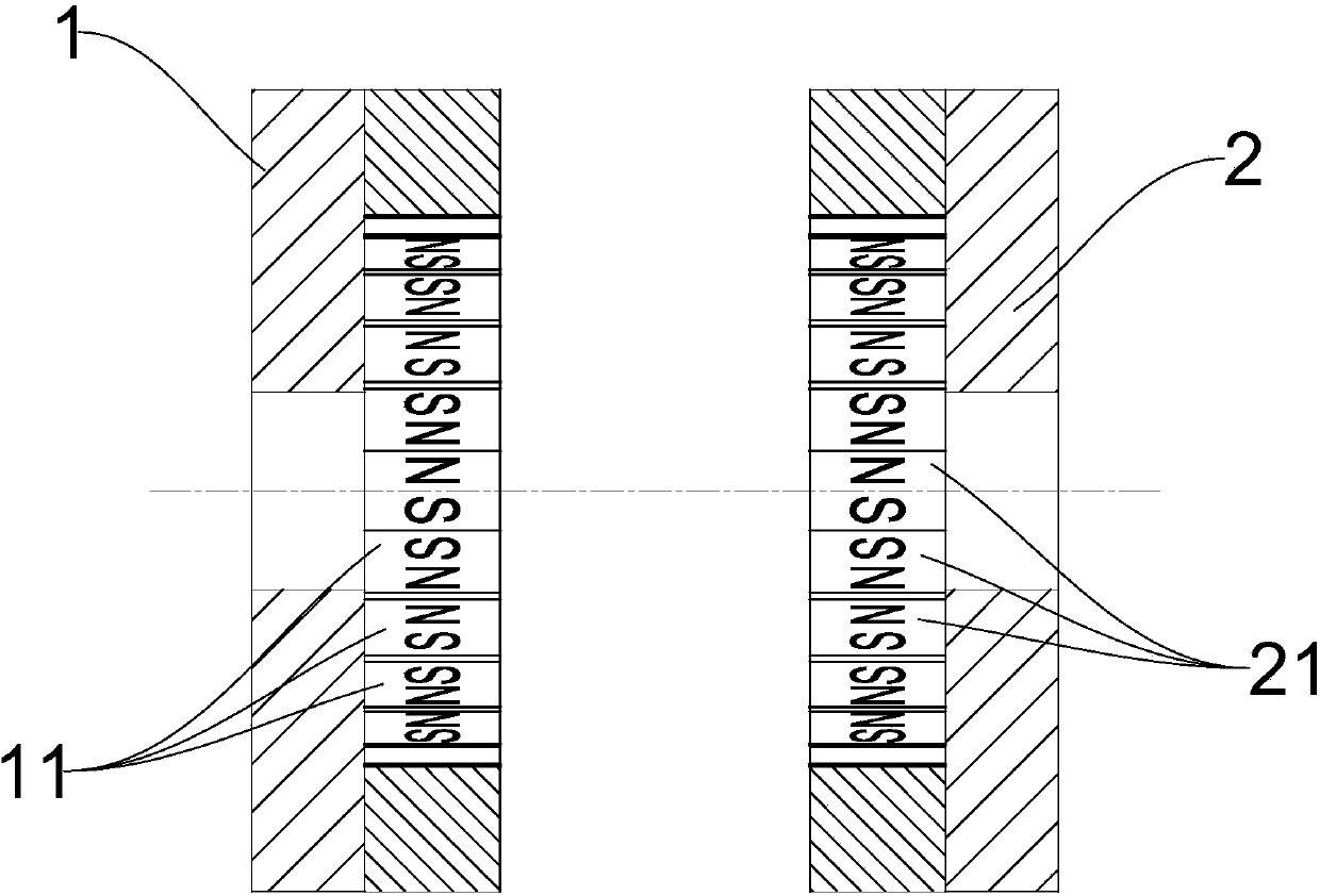
[0073] The magnetic poles of the main end faces of the first permanent magnet 11 and the second permanent magnet 21 are mutually repelled and discharged.

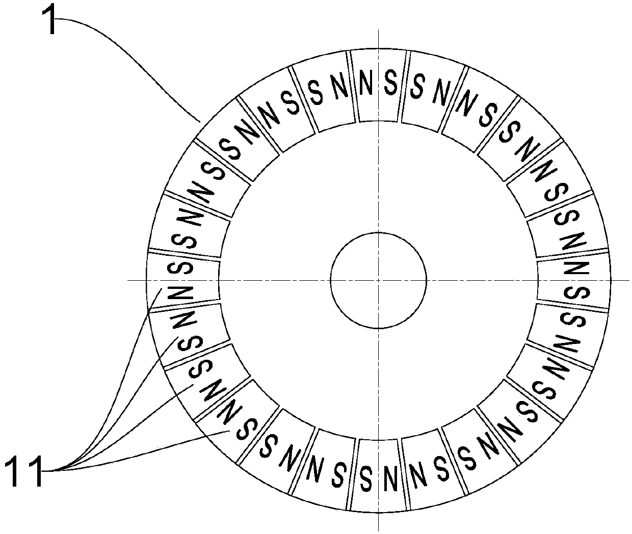
[0074] Such as figure 1 , figure 2 As shown, the first permanent magnet 11 is arranged around the first transmission disc 1, and its side is connected with the first transmission disc 1, and the magnetic poles of the main end faces of the first permanent magnet 11 repel each other to form an arrangement of NS:SN In sequence, a magnetizer is provided between adjacent first permanent magnets 11; the arrangement of the second permanent magnets 21 is the same as that of the first permanent magnets 11 and the first transmission disc 1 and the second transmission disc 2 same size as figure 2 As shown, the first transmission disc 1 and the second transmission disc 2 are as figure 2 Arranged in parallel.

Embodiment 2

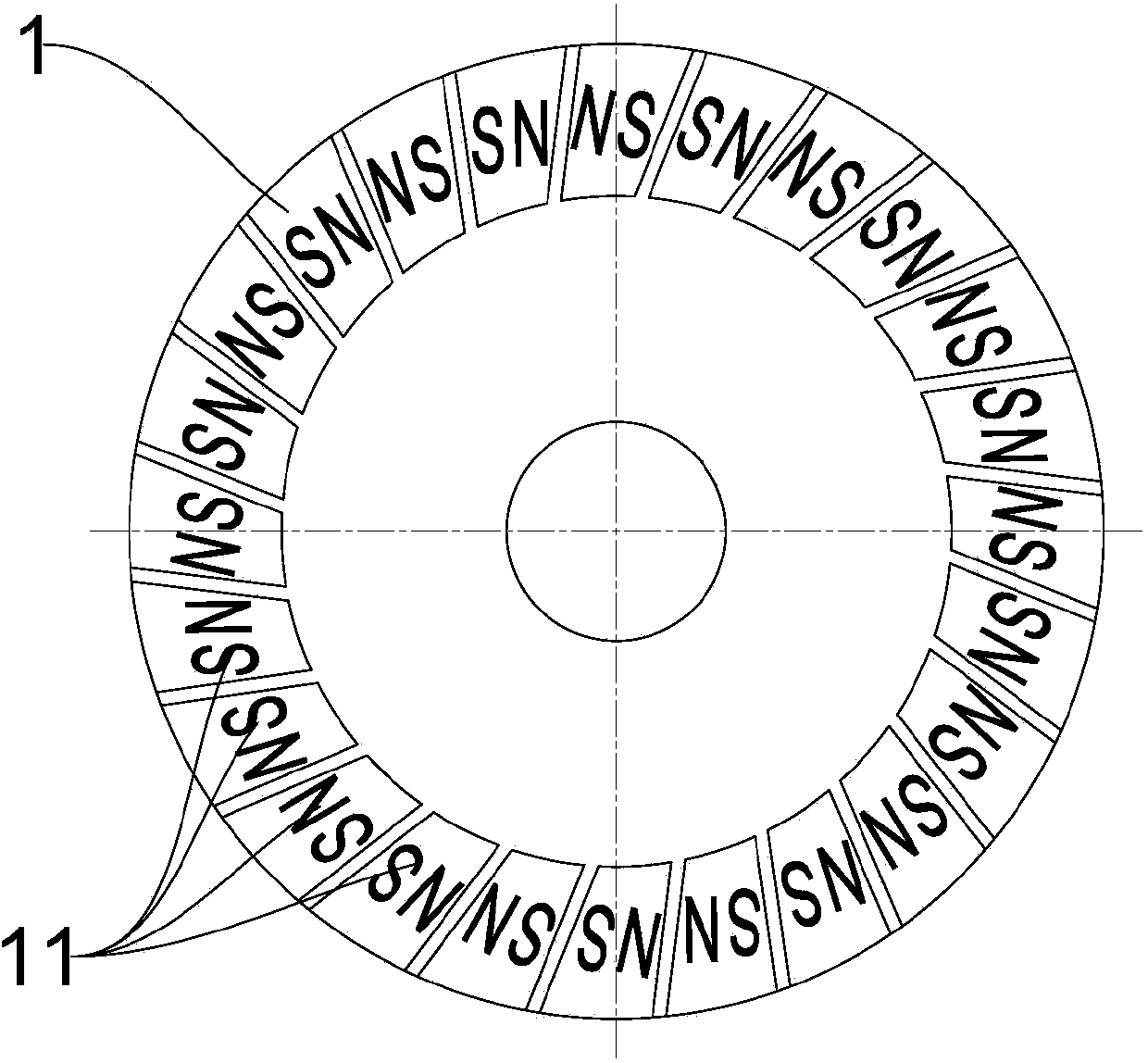
[0076] Such as Figure 5 As shown, the first permanent magnet 11 is arranged in a cylindrical shape in the order of NS: SN, which is larger than the diameter of the cylindrical shape of the second permanent magnet 21 arranged in the order of NS: SN, and the cylindrical shape of the second permanent magnet 21 is Arranged on the inner side of the cylinder formed by the first permanent magnet 11 and arranged coaxially, from Figure 13 It can be seen from the figure that the magnetic poles of the main end faces of the first permanent magnets 11 repel each other and form an arrangement sequence of NS:SN, and a magnetizer is arranged between adjacent first permanent magnets 11; the arrangement of the second permanent magnets 21 It is the same as the arrangement of the first permanent magnet 11 .

Embodiment 3

[0078] Such as Figure 6 , Figure 7 As shown, one end-face magnetic pole of the first permanent magnet 11 is connected to the first transmission disc 1 through a magnetizer, and the other end-face magnetic pole is arranged in the order of N:S:N:S; the arrangement of the second permanent magnet 21 is the same as The arrangement of the first permanent magnet 11 is the same; as Figure 6 As shown, the first transmission disk 1 and the second transmission disk 2 are arranged in parallel, so that the end surface magnetic poles of the first permanent magnet 11 and the end surface magnetic poles of the second permanent magnet 21 are arranged oppositely.


PUM


Abstract

The invention provides a permanent magnet driver. A power disc and a load disc are made of insulating diamagnetic materials or made by combining the insulating diamagnetic materials and materials with other physical properties and are respectively provided with permanent magnets, and the purpose of transmitting torque is realized through using magnetizers to emit magnetic field waves and combining a magnetic focusing effect and the Li's pull and push magnetic circuit theory. The purposes of torque adjustment and speed changing are realized by adjusting the distance between the power disc and the load disc or adjusting the coupling position of the relative magnetic field of the power disc and the load disc, and the main purposes of saving energy and reducing consumption are further realized.

Description

technical field [0001] The invention relates to the field of power transmission, more precisely, it is a permanent magnet driver. Background technique [0002] The permanent magnet eddy current coupler is a common transmission device in the prior art. This transmission device has the advantages of isolating vibration and noise when it is working, but when the permanent magnet eddy current coupler is working, its conductor disk must be There is a speed difference between the permanent magnet and the permanent magnet to cut the magnetic field line of the permanent magnet, change the magnetic flux and direction in the conductor disk, generate high-frequency alternating induction short-circuit current and magnetic eddy current, form an anti-magnetic field effect and achieve torque transmission with the permanent magnet. The existence of short-circuit current and magnetic eddy current makes this kind of permanent magnet eddy current coupler generate serious heat in the process of...

Claims


Application Information

Patent Timeline
Patent Type & Authority Applications(China)
IPC IPC(8): F16H49/00
CPCF16H49/00
Inventor 沈嘉诚陈伟平
Owner 沈嘉诚
Why Eureka
Try Eureka