
Monitoring equipment fixing device with vibration reducing function

A technology of monitoring equipment and fixing devices, which is applied in the direction of mechanical equipment, non-rotational vibration suppression, supporting machines, etc., can solve the problems of increasing the workload of workers, loosening of cameras, consuming a lot of time and physical strength, etc., so as to avoid damage to monitoring equipment and reduce Friction loss and practical improvement effect

Inactive Publication Date: 2014-12-10
CHENGDU BESTVISION TECH
View PDF5 Cites 0 Cited by
  • Summary
  • Abstract
  • Description
  • Claims
  • Application Information

AI Technical Summary

Problems solved by technology

The most common installation method is usually to install pole-type surveillance cameras on main streets or arterial roads and highways. This installation method uses duckbill brackets and iron wires to fix the cameras. However, during long-term use, the wires or The duckbill bracket will rust and cause the camera to become loose, which will affect the quality of information collection or monitoring
Moreover, during the installation or maintenance of many cameras, it takes a lot of time and energy to move the cameras and duckbill brackets up and down continuously, which greatly increases the workload of workers and further increases the total cost of implementing Safe City

Method used


Image

  • Monitoring equipment fixing device with vibration reducing function
  • Monitoring equipment fixing device with vibration reducing function

Examples


Embodiment 1

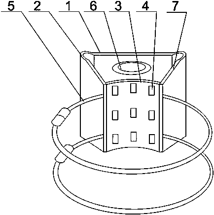
[0022] Such as Figure 1 to Figure 2 As shown, the present invention includes a bottom plate 1 and two obliquely arranged baffles 7, the two ends of the bottom plate 1 are connected to one side of the curved portion, and the other side of the curved portion 2 is connected to the end of the baffle 7, and the two baffles 7 is connected with an arc plate 3, and the inner arc surface of the arc plate 3 is provided with multiple rows of roller groups, and the roller groups are a plurality of rollers 4 arranged at intervals along the vertical direction of the top of the arc plate 3. A plurality of hoops 5 are included, and the hoops 5 pass through the ends of the two baffles 7 and are in contact with the outer arc surface of the arc-shaped plate 3 . As a further improvement of the installation method of the traditional monitor, the present invention first fixes the base plate 1 and the baffle plate 7 on the rod-shaped support structure on the city street through the clamp 5, and the...

Embodiment 2

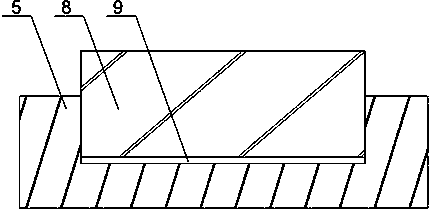
[0025] Such as figure 1 with 2 As shown, this embodiment is based on the embodiment 1, and the inner side of the clamp is provided with an annular groove 9, and a rubber ring 8 protruding from the upper surface of the annular groove 9 is installed in the annular groove. The rod-shaped support structures set up in cities mostly use steel wire rods, and the mounting base is bound to the steel wire rods through clamps 5. However, steel wire rods are prone to the physical characteristics of metal materials, that is, thermal expansion and cold contraction. , for the ordinary clamp fastening method, once the steel wire rod expands with heat and contracts with cold, it will generate multiple forces radiating along the circumferential direction of the wire rod on the wire rod, which will easily cause the stress of the wire rod to be damaged or even Direct fracture; the present invention provides an annular groove 9 in the middle of the clamp 5, and a rubber ring 8 protruding from the...


PUM


Abstract

The invention discloses a monitoring equipment fixing device with a vibration reducing function. The monitoring equipment fixing device comprises a baseplate and two inclined baffle plates, wherein the two ends of the baseplate are connected with one side of a bent part; the other side of the bent part is connected with the ends of the baffle plates; an arched plate is connected between the two baffle plates; multiple rows of roller sets are arranged on the inner arc surface of the arched plate; the roller sets are multiple rollers spaced in the vertical direction of the top end of the arched plate; the monitoring equipment fixing device further comprises a plurality of hoops; and the hoops penetrate through the ends of the two baffle plates, and are contacted with the outer arc surface of the arched plate. The two inclined baffle plates and the baseplate form a saddle-shaped space structure; the arched plate seals an opening of the saddle-shaped space structure; and the ends of the hoops penetrating through the two baffle plates are positioned on the outer arc surface of the arched plate to increase the stability of a mounting base so as to prevent the damage of monitoring equipment caused by instability of a bracket in the use process.

Description

technical field [0001] The invention relates to a monitoring fixing device, in particular to a monitoring equipment fixing device with shock absorption function. Background technique [0002] Safe City utilizes the comprehensive management information public service platform of Safe City, including video surveillance system, digital city management system, road traffic and other systems in the city, and utilizes the city-level data exchange platform to realize resource sharing. The front-end data of the system are collected through the video surveillance system and transmitted to the city and district supervision command and dispatch centers. The management platform of the supervision, command and dispatch center is composed of database server, storage server, management server, alarm server, dispatch control server, streaming media server, Web server, display server and other application servers. The construction of a safe city is first of all the needs of public security ...

Claims


Application Information

Patent Timeline
Patent Type & Authority Applications(China)
IPC IPC(8): F16M13/02F16M11/04F16F15/06
Inventor 黄鹏宇郭振中
Owner CHENGDU BESTVISION TECH
Learn More