LED bulb

A technology of LED light bulbs and bulbs, applied in lighting devices, cooling/heating devices of lighting devices, light sources, etc., can solve the problems of easy air leakage or breakage, difficult helium sealing process, and limited heat exchange capacity, etc., to achieve Reduces thermal resistance, eliminates LED glare, improves cooling and light scattering

Active Publication Date: 2014-12-10
SHANGHAI XINJIE LIGHTING TECH
View PDF7 Cites 3 Cited by
  • Summary
  • Abstract
  • Description
  • Claims
  • Application Information

AI Technical Summary

Problems solved by technology

In the existing LED light bulbs, various cooling structures are provided to cool the LED light-emitting chip. The existing technical solutions include the following four types: (a) exposing the light-emitting surface of the LED light-emitting chip to The disadvantages of using air in the atmosphere for natural cooling are: because the light-emitting chip has a small light-emitting surface, the heat exchange capacity through the air interface is very limited; (b) the most common cooling method is to attach the LED light-emitting chip to a metal or ceramic On the surface, the heat is conducted to the metal surface by contacting the back surface of the light-emitting chip, and the heat conduction efficiency is not ideal; (c) the light-emitting light-emitting chip is enclosed in an airtight transparent bulb, and then filled with good thermal conductivity in the bulb Gas, through the heat-conducting gas (usually helium), the heat from the surface of the light-emitting chip is transferred to the surface of the bulb. Although this method is effective, the sealing process for helium is very difficult, and it can be used to seal the bulb material of helium At present, only fragile glass is known, which is easy to leak or break; (d) pour cooling liquid into the bulb, and then soak the LED light-emitting chip in the cooling liquid to cool down. In practice, it is necessary to ensure the safe insulation of the cooling liquid and the electrical appliances immersed in it during the long-term use of repeated and severe temperature changes.

Method used


Image

  • LED bulb
  • LED bulb
  • LED bulb

Examples


Embodiment Construction

[0029] Specific embodiments of the present invention will be described in detail below in conjunction with the accompanying drawings.

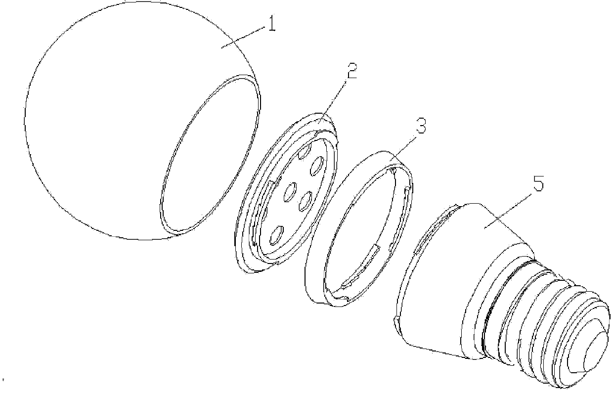
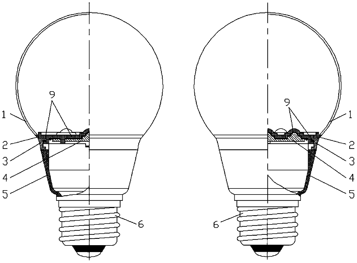
[0030] figure 1 , figure 2 It is a schematic diagram of the overall structure of the LED light bulb of the present invention, including a heat dissipation optical module, a photoelectric conversion module and a locking ring 3. The heat dissipation optical module includes a transparent bulb cover 2 and a bulb shell 1, a transparent bulb cover 2 and a bulb shell 1 Sealed to form a sealed cavity, the sealed cavity is filled with transparent liquid; the photoelectric conversion module includes a cylindrical shell 5, the lower end of the cylindrical shell 5 is equipped with a standard lamp holder 6 connected to an external power supply, and the cylindrical shell 5 contains There is an electronic driver (not shown), the upper end surface of the cylindrical shell 5 is equipped with a planar light-emitting substrate 4, and the LED light-emitting ele...


PUM


Abstract

The invention provides an LED bulb which comprises a photovoltaic conversion module and an optical heat dissipation module, wherein the photovoltaic conversion module is connected with the optical heat dissipation module through a locking ring. The photovoltaic conversion module comprises a barrel-shaped shell which contains an electronic driver, a standard lamp base is installed on the lower end face of the barrel-shaped shell, a planar light-emitting substrate is installed on the upper end face of the barrel-shaped shell, and one mechanical interface is arranged in the peripheral surface of the end, where the planar light-emitting substrate is installed, of the barrel-shaped shell. The optical heat dissipation module comprises an optical input transparent bubble cap cover and an optical output bubble cap, another mechanical interface is correspondingly arranged in the outer side of the transparent bubble cap cover and is connected with the photovoltaic conversion module through the locking ring, the optical input surface of the lower end of the transparent bubble cap cover is matched with the upper end face of the planar light-emitting substrate in external shape, and transparent thermally conductive adhesives are injected into the space between the lower end face of the transparent bubble cap cover and the upper end face of the planar light-emitting substrate. Effective heat dissipation and improvement on light distribution can be achieved through the LED bulb.

Description

【Technical field】 [0001] The invention relates to the field of LED lighting, in particular to an LED light bulb. 【Background technique】 [0002] LED bulbs are recognized as highly efficient light sources, and bulbs and lamps made of such light-emitting chips have been widely used. In the existing LED light bulbs, various cooling structures are provided to cool the LED light-emitting chip. The existing technical solutions include the following four types: (a) exposing the light-emitting surface of the LED light-emitting chip to The disadvantages of using air in the atmosphere for natural cooling are: because the light-emitting chip has a small light-emitting surface, the heat exchange capacity through the air interface is very limited; (b) the most common cooling method is to attach the LED light-emitting chip to a metal or ceramic On the surface, the heat is conducted to the metal surface by contacting the back surface of the light-emitting chip, and the heat conduction eff...

Claims


Application Information

Patent Timeline
Patent Type & Authority Applications(China)
IPC IPC(8): F21S2/00F21V17/10F21V29/00F21Y101/02
Inventor 关德威
Owner SHANGHAI XINJIE LIGHTING TECH
Why Eureka
Try Eureka