System for online real-time monitoring of switch machine indication bar notch width

A real-time monitoring system and switch machine technology, applied in the field of remote monitoring, can solve problems such as too large probe, easy pollution of photoelectric encoder technology, easy damage of detection device, etc.

Active Publication Date: 2014-12-10
赵建明 +1
View PDF7 Cites 7 Cited by
  • Summary
  • Abstract
  • Description
  • Claims
  • Application Information

AI Technical Summary

Problems solved by technology

[0003] The existing monitoring methods for the gap width of the indicator rod all have their shortcomings: such as the touch bead sensor technology and the spring displacement sensor technology, the detection device is easily damaged, the photoelectric encoder technology is easily polluted and the accuracy is reduced, and the reflective optical fiber displacement Sensor technology and Hall displacement sensor technology. The probe is too large and inconvenient to install. The camera technology method does not quantify the detection results and requires manual judgment to indicate the width of the rod gap.
[0004] At the same time, the existing data acquisition methods generally cannot realize real-time data transmission. Usually, the data is stored on the memory card of the acquisition device, and then manually accessed, which has low efficiency and insufficient real-time performance.
[0005] In addition, the existing monitoring methods usually store the data in the monitoring center, which is displayed on the display screen of the monitoring center, and it is impossible to obtain real-time monitored gap data at any place

Method used


Image

  • System for online real-time monitoring of switch machine indication bar notch width
  • System for online real-time monitoring of switch machine indication bar notch width
  • System for online real-time monitoring of switch machine indication bar notch width

Examples


Embodiment 1

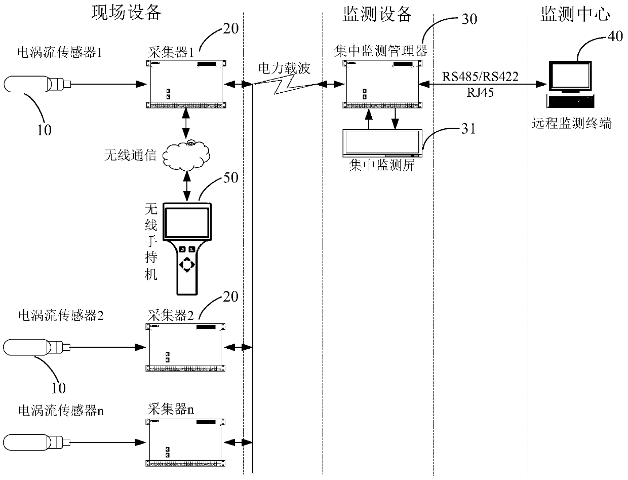
[0067] see figure 1 , the present invention discloses an online real-time monitoring system for the notch width of a railway switch switch machine, said monitoring system comprising: an eddy current sensor 10, a collector 20, a centralized monitoring manager 30, a remote monitoring center 40, and a wireless handset 50; eddy current sensors 10, collectors 20, centralized monitoring managers 30, and wireless handsets 50 can generally be multiple. One collector 20 can be connected to multiple eddy current sensors 10 , one centralized monitoring manager 30 can be connected to multiple collectors 20 , and the remote monitoring center 40 can be connected to one or more centralized monitoring managers 30 .

[0068] 【Eddy current sensor】

[0069] The function of the eddy current sensor 10 is to detect the gap between the inspection post and the gap of the inspection block. The eddy current sensor 10 includes an eddy current probe and an eddy current circuit; the eddy current probe c...

Embodiment 2

[0084] see Figure 5 The difference between this embodiment and Embodiment 1 is that in this embodiment, the eddy current sensor includes: an eddy current probe and an eddy current circuit, the eddy current probe is connected to the eddy current circuit; the eddy current circuit includes an oscillator module , Detection module, temperature compensation module, output buffer stage module.

[0085] The eddy current sensor uses a high-frequency oscillating current to pass through the eddy current probe to generate an alternating magnetic field at the head of the eddy current probe. When a metal conductor moves within the effective range of this alternating magnetic field, the magnetic field will change with the movement of the metal. Change, which is converted into a voltage or current change and passed to the collector module of the monitoring system.

[0086] The oscillator module is responsible for generating an oscillating signal and outputting it to the wave detection modul...

Embodiment 3

[0093] see Figure 6 The difference between this embodiment and Embodiment 2 is that in this embodiment, the oscillator module, wave detection module, temperature compensation module, and output buffer stage module are connected in sequence.

[0094] The oscillator module adopts the principle of a capacitor three-point oscillator, mainly including a first resistor R1, a second resistor R2, a third resistor R3, a first capacitor C1, a second capacitor C2, a third capacitor C3, and a fourth capacitor C4. Transistor Q1, and eddy current coil L1; wherein, the first end of the first resistor R1 is connected to the power supply VDD, the second end of the second resistor R2 is grounded, and the second end of the first resistor R1 and the first end of the second resistor R2 are respectively Connect the base of the amplifying transistor Q1 to provide a bias voltage for the amplifying transistor Q1; the second capacitor C2, the third capacitor C3, the fourth capacitor C4, and the eddy c...


PUM


Abstract

The invention discloses a system for online real-time monitoring of switch machine indication bar notch width. The system comprises eddy current sensors, collectors, a central monitoring manager and remote monitoring centers. Each eddy current sensor comprises an eddy current probe and an eddy current circuit; the eddy current probe is used for converting a gap between a check post and a notch of a check block into an eddy current signal, and the eddy current signal is processed by the eddy current circuit and output. The collectors are used for collecting data output by the eddy current sensors. The central monitoring managers are connected with the collectors through power cords and are used for receiving data collected by the collectors, in a power line carrier manner. The remote monitoring center is connected with one or multiple central monitoring centers and is used for receiving data transmitted by the central monitoring managers. The system has the advantages that stability and reliability are improved, false alarm rate and false negative rate are zero, the eddy current sensors are higher in reliability, sensitivity, resolution, response speed and interference resistance during long-term operation, and the system is suitable for various switch machines and various application environments.

Description

technical field [0001] The invention belongs to the technical field of remote monitoring, and relates to a monitoring system, in particular to an online real-time monitoring system for the notch width of a display bar of a railway switch point machine. Background technique [0002] Whether the working state of the railway switch machine is normal or not is very important to ensure the normal operation of the railway. The research on the monitoring of the working state of the railway switch machine has never been interrupted for more than ten years. At present, the main methods of monitoring the working state of the switch machine are The parameters are the switching resistance and the notch width of the indicating rod. The converting resistance is an indirect expression of the degree of closeness of the point rail of the switch machine, and the width of the notch of the indicating rod is a direct expression of the degree of closeness of the point rail of the switch machine. ...

Claims


Application Information

Patent Timeline
Patent Type & Authority Applications(China)
IPC IPC(8): G01B7/02
Inventor 张长生王予平赵建明吴旺生陈志雄魏涛刘玉玲
Owner 赵建明
Why Eureka
Try Eureka