
On-line real-time monitoring system for the gap width of switch switch machine
A real-time monitoring system and monitoring system technology, applied in the field of remote monitoring, can solve the problems of inconvenient installation, easily damaged detection devices, low efficiency, etc.
- Summary
- Abstract
- Description
- Claims
- Application Information
AI Technical Summary
Problems solved by technology
Method used
Image

Examples
Embodiment 1
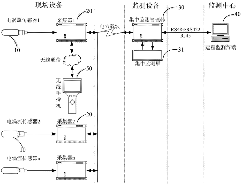
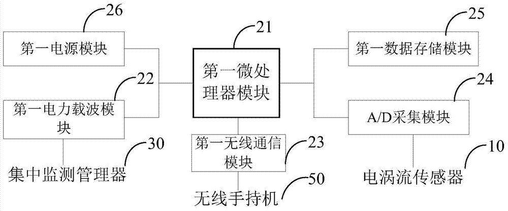
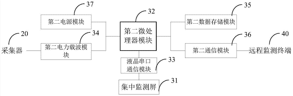
[0067] see figure 1 , the present invention discloses an online real-time monitoring system for the notch width of a railway switch switch machine, said monitoring system comprising: an eddy current sensor 10, a collector 20, a centralized monitoring manager 30, a remote monitoring center 40, and a wireless handset 50; eddy current sensors 10, collectors 20, centralized monitoring managers 30, and wireless handsets 50 can generally be multiple. One collector 20 can be connected to multiple eddy current sensors 10 , one centralized monitoring manager 30 can be connected to multiple collectors 20 , and the remote monitoring center 40 can be connected to one or more centralized monitoring managers 30 .
[0068] 【Eddy current sensor】
[0069] The function of the eddy current sensor 10 is to detect the gap between the inspection post and the gap of the inspection block. The eddy current sensor 10 includes an eddy current probe and an eddy current circuit; the eddy current probe c...
Embodiment 2
[0084] see Figure 5 The difference between this embodiment and Embodiment 1 is that in this embodiment, the eddy current sensor includes: an eddy current probe and an eddy current circuit, the eddy current probe is connected to the eddy current circuit; the eddy current circuit includes an oscillator module , Detection module, temperature compensation module, output buffer stage module.
[0085] The eddy current sensor uses a high-frequency oscillating current to pass through the eddy current probe to generate an alternating magnetic field at the head of the eddy current probe. When a metal conductor moves within the effective range of this alternating magnetic field, the magnetic field will change with the movement of the metal. Change, which is converted into a voltage or current change and passed to the collector module of the monitoring system.
[0086] The oscillator module is responsible for generating an oscillating signal and outputting it to the wave detection modul...
Embodiment 3
[0093] see Figure 6 The difference between this embodiment and Embodiment 2 is that in this embodiment, the oscillator module, wave detection module, temperature compensation module, and output buffer stage module are connected in sequence.
[0094] The oscillator module adopts the principle of a capacitor three-point oscillator, mainly including a first resistor R1, a second resistor R2, a third resistor R3, a first capacitor C1, a second capacitor C2, a third capacitor C3, and a fourth capacitor C4. Transistor Q1, and eddy current coil L1; wherein, the first end of the first resistor R1 is connected to the power supply VDD, the second end of the second resistor R2 is grounded, and the second end of the first resistor R1 and the first end of the second resistor R2 are respectively Connect the base of the amplifying transistor Q1 to provide a bias voltage for the amplifying transistor Q1; the second capacitor C2, the third capacitor C3, the fourth capacitor C4, and the eddy c...
PUM
 Abstract
Description
Claims
Application Information