Measuring system for expansion coefficient of material

A technology of expansion coefficient and measurement system, applied in the direction of material thermal expansion coefficient, phase influence characteristic measurement, etc., can solve problems such as no research on thermal expansion coefficient

Inactive Publication Date: 2014-12-10
TSINGHUA UNIV
View PDF5 Cites 14 Cited by
  • Summary
  • Abstract
  • Description
  • Claims
  • Application Information

AI Technical Summary

Problems solved by technology

At present, there is no research on how to measure the thermal expansion coeffici

Method used


Image

  • Measuring system for expansion coefficient of material
  • Measuring system for expansion coefficient of material
  • Measuring system for expansion coefficient of material

Examples


Embodiment 1

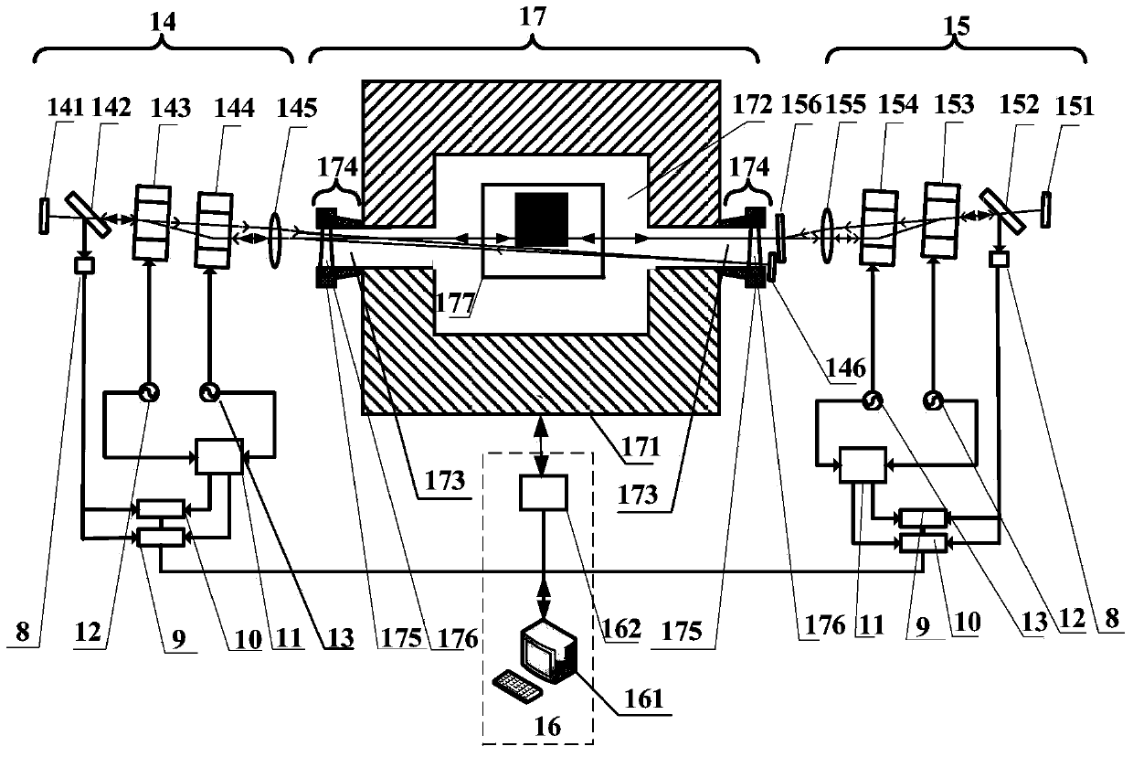
[0040] Such as figure 2 As shown, Embodiment 1 of the present invention includes first and second solid microchip laser feedback interferometer optical systems 14, 15 and an electrical measurement and electronic control system 16, and a solid microchip laser feedback interferometer optical system is arranged between The heating furnace 17, the heating furnace 17 includes a furnace 171, a cavity 172 is arranged inside the furnace 171, a perforation 173 is arranged symmetrically outward on the two opposite sides of the cavity 172, and a perforated packaging structure 174 is fixedly arranged on the outer end of each perforation 173 , the outer end of each perforated packaging structure 174 fixes a window 176 through a window holder 175, a sample stage device 177 capable of placing the sample to be tested is also arranged in the cavity, and a heating element is also fixedly suspended in the furnace 171 and a temperature sensor (not shown in the figure).

[0041] The first solid-st...

Embodiment 2

[0071] Such as Figure 4As shown, the structure of Embodiment 2 of the present invention is basically the same as that of Embodiment 1, and it includes first and second solid-state microchip laser feedback interferometer optical systems 18, 15 and electrical measurement and electrical control system 16. The difference is The structure of the first solid microchip laser feedback interferometer optical system 18 adopted in this embodiment is different. The first solid microchip laser feedback interferometer optical system 18 in the present embodiment adopts the second solid microchip in embodiment The optical system 15 of the laser feedback interferometer has the same structure, and the structure and principle of the electric measurement and electric control system 16 are the same as those in Embodiment 1, and will not be repeated here.

[0072] The first solid-state microchip laser feedback interferometer optical system 18 of the present embodiment includes several optical elem...

Embodiment 3

[0084] Such as Figure 6 As shown, Embodiment 3 of the present invention includes a microchip laser feedback interferometer optical system 19 and an electrical measurement and electrical control system 16, and a heating furnace 20 is arranged below the solid microchip laser feedback interferometer optical system 19; the heating furnace 20 includes A furnace 201, a cavity 202 is arranged in the furnace 201, a perforation 203 is arranged on the top of the cavity 202 extending outward, and a perforation sealing structure 204 is fixedly arranged on the outer end of the perforation 203, and the outer end of the perforation sealing structure 204 passes through a window The sheet holding seat 205 fixes a window 206, and a sample stage device 207 capable of placing a reference object and a sample to be tested is also arranged in the cavity 202, and a heating element and a temperature sensor (not shown in the figure) are also fixedly suspended in the furnace 201. ); the electrical meas...


PUM


Abstract

The invention relates to a measuring system for the expansion coefficient of a material. The measuring system is characterized by comprising two solid microchip laser feedback interferometer optical systems and an electrical logging and electric control system, wherein a heating furnace is arranged between the two solid microchip laser feedback interferometer optical systems and comprises a furnace chamber; a cavity is formed in the furnace chamber; a perforating hole is symmetrically formed in the two opposite sides of the cavity outward respectively; a perforating hole packaging structure is fixedly arranged at the outer end part of each perforating hole; a window plate is fixed outside each perforating hole packaging structure through a window plate clamping seat; a sample table device capable of accommodating a sample to be measured is further arranged in the cavity body; a heating element and a temperature sensor are fixedly arranged on the inner wall of the furnace chamber in a suspended mode. The measuring system for coefficient of liner expansion has the advantages of complete non-contact, high precision, large temperature measuring range and high resistance to shock, and is particularly suitable for a relatively low surface reflecting material. The measuring system can be widely applied to large temperature range and high precision measurement of expansion coefficient of various materials.

Description

technical field [0001] The invention relates to a measurement system for the expansion coefficient of a material, in particular to a measurement system for the expansion coefficient of a material based on a solid microchip laser feedback interferometer. Background technique [0002] Material expansion coefficient is one of the thermal physical properties of materials, and it is an important characteristic quantity to characterize material properties. The measurement of material expansion coefficient is of great significance in practical engineering and basic research. In recent years, the measurement of the expansion coefficient of materials has attracted interest in some important fields, such as precision photolithography, providing transfer standards for other secondary dilatometers (push rods or similar devices), and providing high-temperature expansion of special materials. Coefficient technical standards, etc., therefore, put forward higher requirements for measurement...

Claims


Application Information

Patent Timeline
IPC IPC(8): G01N21/45G01N25/16
Inventor 张书练郑发松谈宜东
Owner TSINGHUA UNIV
Why Eureka
Try Eureka