
Eight-beam symmetrical silicon micro-accelerometer

A micro-accelerometer, accelerometer technology, applied in the direction of measurement of acceleration, velocity/acceleration/shock measurement, measurement device, etc., can solve problems such as affecting the long-term stability of the accelerometer, difficult to obtain a mass mass, affecting the performance of the accelerometer, etc. Achieve the effect of improving long-term stability, reducing thermal expansion coefficient mismatch, and good structural size control

Inactive Publication Date: 2014-12-10
INST OF ELECTRONICS ENG CHINA ACAD OF ENG PHYSICS
View PDF5 Cites 8 Cited by
  • Summary
  • Abstract
  • Description
  • Claims
  • Application Information

AI Technical Summary

Problems solved by technology

In this way, on the one hand, the difficulty of the process is increased to reduce the yield, and on the other hand, it is difficult to obtain a mass block with a large mass, which affects the improvement of the performance of the accelerometer.
For the general "mass block-cantilever beam" structure, the center of gravity of the mass block is not the center of gravity of the entire structure, so the stress at the connection part between the cantilever beam and the fixed end is very concentrated, which greatly affects the long-term stability of the accelerometer
Due to structural asymmetry, mechanical thermal noise, and limited weight of mass blocks, there are some problems in linearity and accuracy of micro accelerometers.

Method used


Image

  • Eight-beam symmetrical silicon micro-accelerometer
  • Eight-beam symmetrical silicon micro-accelerometer
  • Eight-beam symmetrical silicon micro-accelerometer

Examples


Embodiment Construction

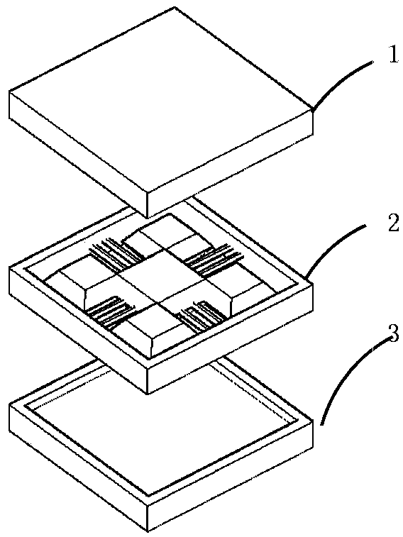
[0045] figure 1 It is a structural diagram of the eight-beam symmetrical silicon micro-accelerometer of the present invention, including three parts: an upper electrode plate 1, a sensitive chip 2 and a lower electrode plate 3, and the wafer-level packaging of the entire chip is realized through silicon-silicon fusion bonding. A polygonal mass block for sensing inertial acceleration is set inside the sensitive chip. Eight cantilever beams with the same structure and the same structure located in the center plane of the polygonal mass block in the thickness direction are symmetrically distributed around the mass block. The mass block is connected to the frame through the cantilever beam; silicon electrodes The board and the sensitive chip are insulated by silicon dioxide and connected by silicon-silicon fusion bonding. The section of the cantilever beam is a parallelogram, and the length ratio of the long diagonal and the short diagonal of the parallelogram is in the range of 1...


PUM


Abstract

The invention provides an eight-beam symmetrical silicon micro-accelerometer. The capacitive micro-accelerometer comprises three portions of an upper silicon electrode plate, a sensitive chip and a lower silicon electrode plate from top to bottom, wherein the sensitive chip is of a micro-structure of 'mass block-cantilever beams'; eight cantilever beams are provided, and symmetrically distributed around a mass block, and the mass block is located at a middle horizontal position; the thickness of the mass block is the same as that of the adopted silicon slice, and the shape is a polygon so as to effectively utilize the space, thus the quality is greatly improved, and a lower device noise and a higher sensitivity can be obtained; the micro-accelerometer adopts an all-silicon process, the silicon electrode plates are bonded with the sensitive chip through silicon-silicon fusion, thus problems of thermal expansion coefficient mismatching and the like can be reduced; the patterns of the mass block and the beams are formed on the surface of the silicon slice through a double-layer SiO2 process, thus deep-groove photoetching is avoided. The eight-beam symmetrical silicon micro-accelerometer provided by the invention is high in stability, low in device noise, and capable of improving the measurement accuracy of the accelerometer.

Description

technical field [0001] The invention belongs to the technical field of micro-electro-mechanical systems, and in particular relates to an eight-beam symmetrical silicon micro-accelerometer, which has high precision, good linearity and good long-term stability. Background technique [0002] With the increasing development of markets such as navigation systems, oil exploration, gravity gradiometers, and seismic monitoring, the demand for micro-accelerometers with high precision and high stability (μg level) is becoming stronger and stronger. Various micro accelerometers for high precision and high stability are constantly being developed. Among them, silicon microcapacitive accelerometers have the advantages of high sensitivity, good noise performance, low drift, low temperature sensitivity, etc., so in the field of accelerometers Research on silicon microcapacitive accelerometers accounts for a considerable part. [0003] The basic working principle of the silicon microcapaci...

Claims


Application Information

Patent Timeline
Patent Type & Authority Applications(China)
IPC IPC(8): G01P15/125
Inventor 唐彬谢国芬席仕伟程永生张德姚明秋
Owner INST OF ELECTRONICS ENG CHINA ACAD OF ENG PHYSICS
Learn More