Single-component fiber-optic geophone, three-component fiber-optic microseismic geophone comprising same and three-component fiber-optic microseismic detection array also comprising same

A fiber optic detector, single-component technology, applied in seismic signal receivers and other directions, can solve the problems of large sensor volume, complex downhole system, low sensitivity, etc., and achieve the effect of high sensitivity, improved sensitivity, and strong wavelength division multiplexing capability.

Inactive Publication Date: 2014-12-10
HARBIN INST OF TECH
View PDF5 Cites 23 Cited by
  • Summary
  • Abstract
  • Description
  • Claims
  • Application Information

AI Technical Summary

Problems solved by technology

[0005] The present invention aims to solve the problems of complex downhole system, low sensitivity and large sensor volume of existing optical fiber detectors, and now provides sin

Method used


Image

  • Single-component fiber-optic geophone, three-component fiber-optic microseismic geophone comprising same and three-component fiber-optic microseismic detection array also comprising same
  • Single-component fiber-optic geophone, three-component fiber-optic microseismic geophone comprising same and three-component fiber-optic microseismic detection array also comprising same
  • Single-component fiber-optic geophone, three-component fiber-optic microseismic geophone comprising same and three-component fiber-optic microseismic detection array also comprising same

Examples


specific Embodiment approach 1

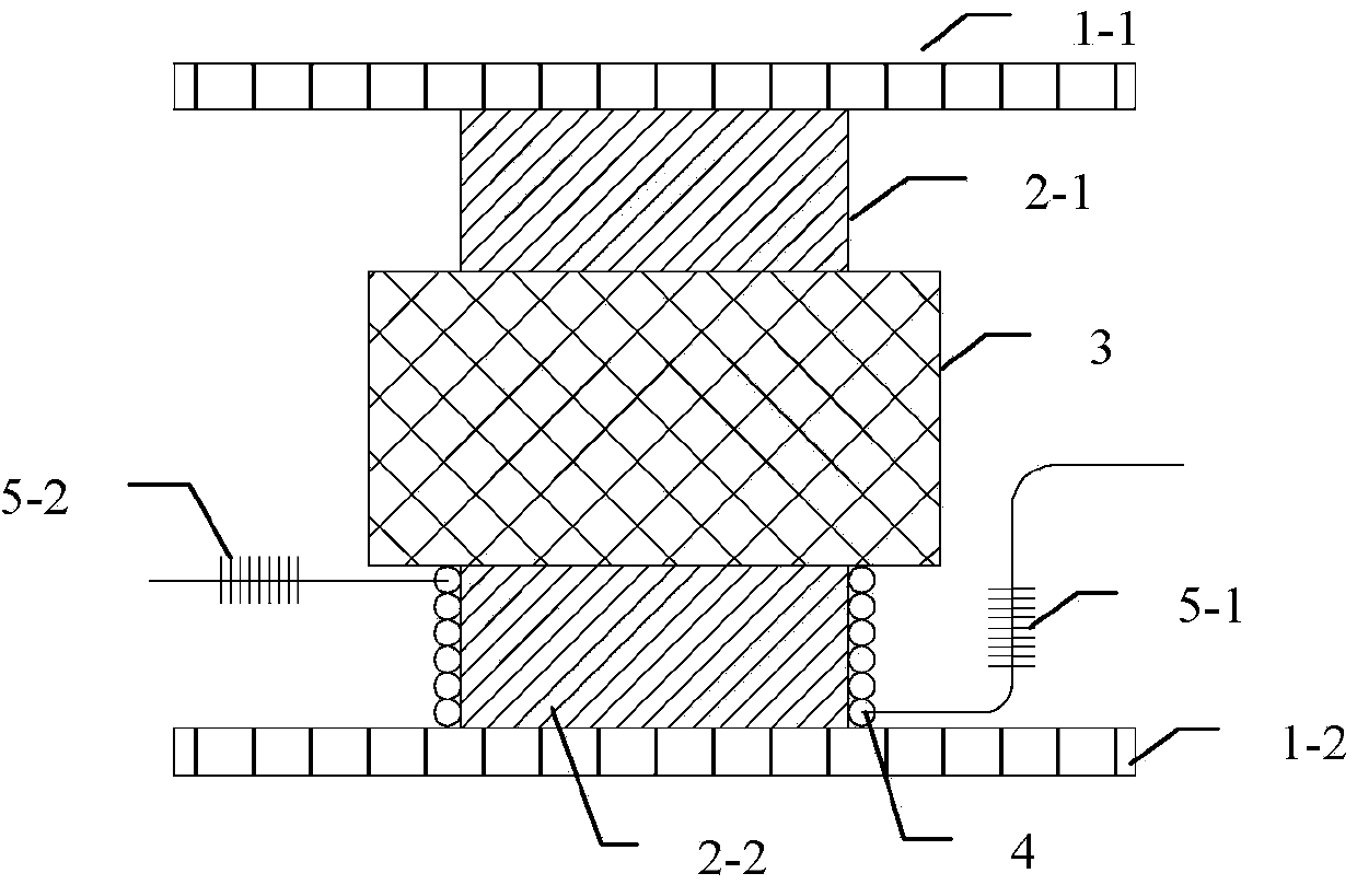
[0024] Specific implementation mode one: refer to figure 1 Specifically explain this embodiment, the single-component optical fiber detector described in this embodiment includes: No. 1 end frame 1-1, No. 2 end frame 1-2, No. 1 rubber column 2-1, and No. 2 rubber column 2 -2, quality block 3, fiber optic coil 4, No. 1 fiber Bragg grating 5-1 and No. 2 fiber Bragg grating 5-2;

[0025] One end of the No. 1 rubber column 2-1 and one end of the No. 2 rubber column 2-2 are respectively fixed on two parallel surfaces of the mass block 3, and the other end of the No. 1 rubber column 2-1 is fixed on the No. 1 end frame 1 -1 side, the other end of the No. 2 rubber column 2-2 is fixed on the side of the No. 2 end frame 1-2, the optical fiber coil 4 is wound on the surface of the No. 2 rubber column 2-2, and one end of the optical fiber coil 4 is connected to One end of the No. 1 Fiber Bragg Grating 5-1 and the other end of the Fiber Coil 4 are connected to one end of the No. 2 Fiber B...

specific Embodiment approach 2

[0034] Specific embodiment 2: This embodiment is a further description of the single-component fiber detector described in Specific Embodiment 1. In this embodiment, the center of the No. 1 Fiber Bragg Grating 5-1 and the No. 2 Fiber Bragg Grating 5-2 same wavelength.

specific Embodiment approach 3

[0035] Specific embodiment three: this embodiment is a further description of the single-component optical fiber detector described in specific embodiment one. In this embodiment, the shape of the mass block 3 is a cube or a cylinder, and the mass block 3 and The contact end surface area of ​​the two rubber columns is larger than the end surface area of ​​the two rubber columns.


PUM


Abstract

The invention relates to a single-component fiber-optic geophone, a three-component fiber-optic microseismic geophone comprising the same and a three-component fiber-optic microseismic detection array also comprising the same, belongs to the technical field of fiber-optic sensors and aims to solve the problems that an unground system of the existing fiber-optic geophone is complex, the existing fiber-optic geophone is low in sensitivity and sensors are large in size. The single-component fiber-optic geophone is characterized in that two fiber Bragg gratings and a fiber coil form a fiber grating F-P (Fabry-Perot) cavity structure; sensitivity of the geophone is effectively improved. A faraday rotator mirror is replaced by low-reflectivity FBGs (fiber Bragg gratings) serving as a reflector; the structure is greatly simplified. In addition, compared with the traditional fiber Bragg grating with the F-P cavity, the single-component fiber-optic geophone has high sensitivity. The single-component fiber-optic geophone is applicable to microseismic monitoring.

Description

technical field [0001] The invention belongs to the technical field of optical fiber sensors, in particular to an optical fiber detector. Background technique [0002] At present, there are fewer and fewer medium and high permeability oil and gas fields put into development in my country, and more and more low permeability oil fields, and most of the undeveloped reserves are concentrated in low permeability reservoirs. Therefore, the success or failure of low-permeability oilfield development is closely related to the development of my country's petroleum industry. In the development process of low-permeability oil and gas fields, tight oil reservoirs, and shale gas, fracturing is an important measure to increase production. The orientation and scale of fractures generated by fracturing and natural fractures are an important reference for well pattern deployment. [0003] Conventional fracturing monitoring technologies, such as inclination measurement, well temperature meas...

Claims


Application Information

Patent Timeline
IPC IPC(8): G01V1/18G01V1/20
Inventor 张洪涛宋文平李隆球刘丽丽何俊张广玉
Owner HARBIN INST OF TECH
Why Eureka
Try Eureka