Optical module component coupling device

A technology of coupling device and optical module, which is applied in the coupling direction of optical waveguide, can solve the problems that affect the coupling accuracy of products, the height deviation of threaded holes, and the low coupling efficiency, so as to improve the adjustment accuracy and positioning speed, ensure the coaxiality, The effect of improving productivity

Active Publication Date: 2014-12-10
四川华拓光通信股份有限公司 +1
View PDF4 Cites 0 Cited by
  • Summary
  • Abstract
  • Description
  • Claims
  • Application Information

AI Technical Summary

Problems solved by technology

[0003] In other words, the traditional optical module component coupling device takes into account the functions of guidance and force transmission at the same time when performing the coupling action, but the fit between the threads is a clearance fit, and accurate guidance cannot be guaranteed during the entire coupling process; and during the component coupling process A certain axial preload is required between the laser emitting end and the product components, so the coupling device of the traditional optical module component is designed to form a certain angle between the threaded hole of the screw rod and the horizontal plane (such as the above-mentioned patent) to ensure the tightness between the laser emitting end and the components. Due to the axial preload, the four threaded holes perpendicular to each other must be processed independently from four directions. Due to the constraints of the current processing level, it is impossible to meet the coupling requirements of the optical module component for micron-level coaxiality, which may lead to four The threaded holes independently processed in two directions may have deviations in height or other factors, which will affect the coupling accuracy of the product; further, the positioning height of the laser emitting end needs to be adjusted for different types of optical module components, while traditional optical module components coupling The direct adjustment of the device through the axial sliding of the lower base cannot meet the accuracy requirements of 0.1 mm in height and the requirements of rapid positioning
In summary, the coupling accuracy of the traditional optical module component coupling device of the above patent is not high, and the coupling efficiency is too low

Method used


Image

  • Optical module component coupling device
  • Optical module component coupling device

Examples


Embodiment Construction

[0029] The present invention will be further described in detail below with reference to the accompanying drawings, so that those skilled in the art can implement it with reference to the text of the description.

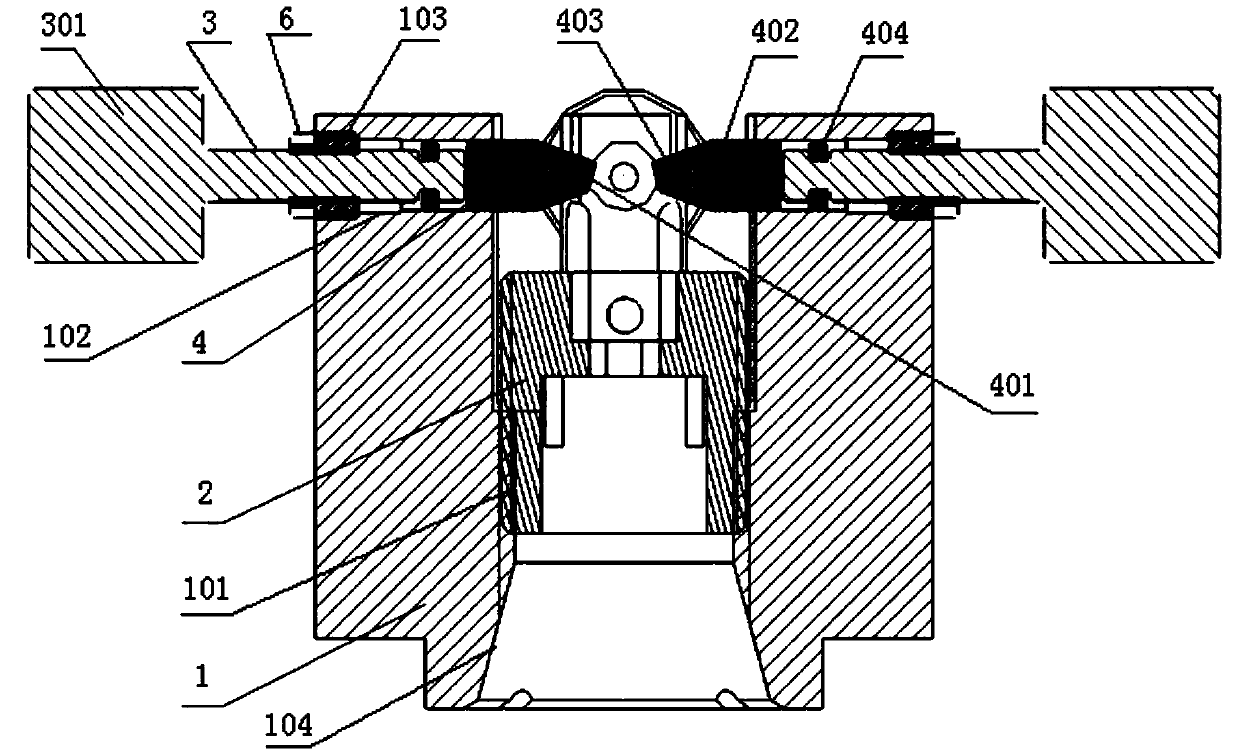
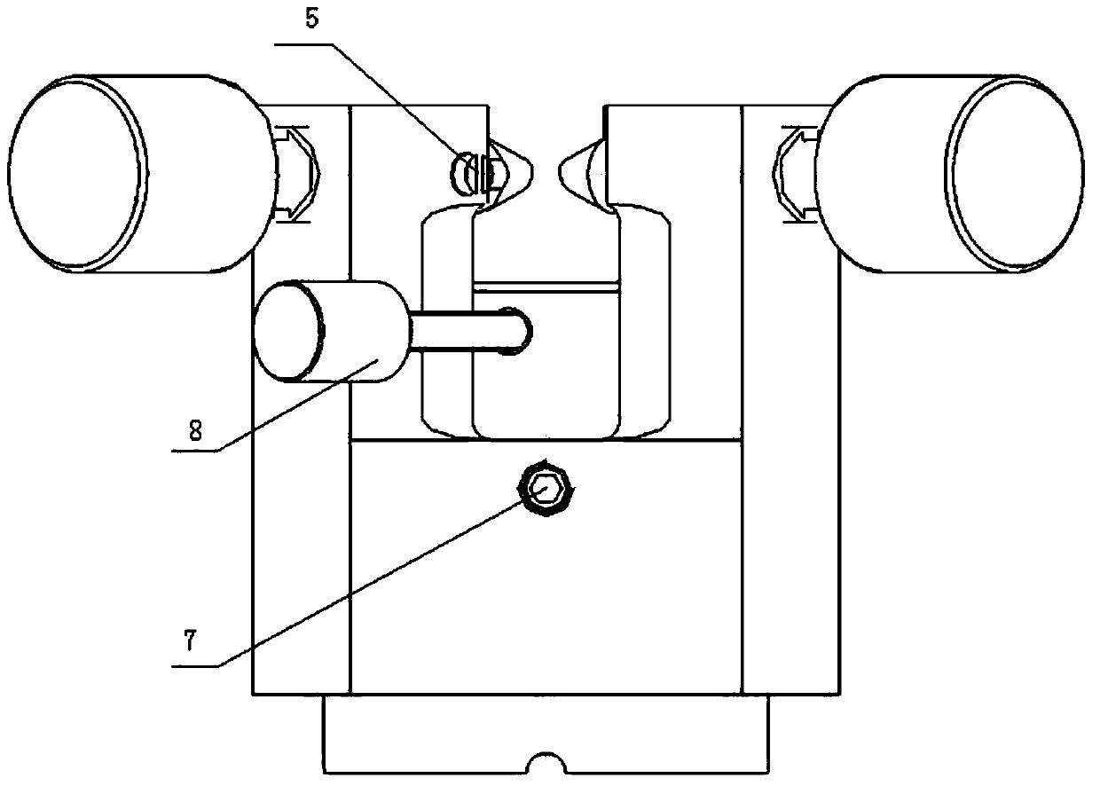
[0030] Such as Figure 1-2 As shown, the present invention provides an optical module assembly coupling device, which includes:

[0031] The upper base 1 for installing the light receiving device is hollow and the lower end is provided with an internal threaded hole 101; the lower base 2 for installing the light emitting device is provided with external threads on its outer circumference; wherein the lower base passes The external thread is connected to the internal threaded hole of the upper base, and the upper end of the upper base is provided with at least two horizontal through holes 102 extending radially along the upper base and penetrating the wall surface of the upper base. A lead screw 3 is threadedly connected; the lead screw has a guide pin 4 at one end close...


PUM


Abstract

The invention discloses an optical module component coupling device which comprises an upper base and a lower base. The upper base is used for mounting an optical receiver, the inside of the upper base is hollow, an internal threaded hole is formed in the lower end of the upper base, the lower base is used for mounting an optical transmitter, an external thread is arranged on the periphery of the lower base, the lower base is connected into the internal threaded hole of the upper base through the external thread, at least two horizontal through holes are formed in the upper end of the upper base, radially extend along the upper base and penetrate the wall of the upper base, each horizontal through hole is connected with a guide screw rod in a threaded manner, a guide pin is coupled at one end of each guide screw rod close to the middle of the upper base and provided with an inclined end face and a lateral plane, and the lateral plane of each guide pin is abutted by a first screw fixed onto the upper base, so that the corresponding inclined end face constantly faces the optical transmitter positioned on the lower base. A traditional coupling device is numerously improved, so that the coupling precision of the optical module component coupling device is improved, and production efficiency is ensured.

Description

Technical field [0001] The invention belongs to the field of optical communication device processing, and in particular relates to a high-precision, high-precision optical module assembly coupling device. Background technique [0002] At present, the traditional optical module assembly coupling device generally first fixes the laser emitting end, and then directly tightens and sets the center coupling assembly by adjusting the four direction knobs that are perpendicular to each other. For example, the patent application number 201220575563.X is a non-adhesive coupling fixture, which discloses a traditional device for coupling optical module components. The coupling device includes four mutually perpendicular and centrally symmetrical screws. There is a certain angular relationship between the bases, so that the screw has a downward pressure while holding the product. [0003] In other words, the traditional optical module component coupling device takes into account the functions ...

Claims


Application Information

Patent Timeline
Patent Type & Authority Applications(China)
IPC IPC(8): G02B6/42
Inventor 范巍刘金
Owner 四川华拓光通信股份有限公司
Why Eureka
Try Eureka