
Unfolding release device of rod antenna

A release device and antenna technology, applied in the field of space-borne antennas, can solve the problems of reducing the working reliability of the mechanism, large additional mass, complex structure, etc., and achieve the effects of small weight, increased reliability, and avoidance of blocking

Active Publication Date: 2014-12-10
INST OF ELECTRONICS CHINESE ACAD OF SCI +1
View PDF4 Cites 18 Cited by
  • Summary
  • Abstract
  • Description
  • Claims
  • Application Information

AI Technical Summary

Problems solved by technology

The drive of the spaceborne antenna deployment device mainly includes motor drive, pneumatic drive, spring drive, etc. The motor and pneumatic drive have relatively large additional mass and complex structure, which brings a lot of pressure to the satellite's lightweight and reduces the cost of the satellite. Institutional work reliability

Method used


Image

  • Unfolding release device of rod antenna
  • Unfolding release device of rod antenna
  • Unfolding release device of rod antenna

Examples


Embodiment Construction

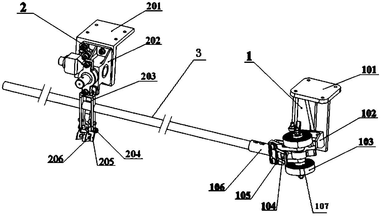
[0022] See attached figure 1 , the deployment and release device of the rod antenna, which includes: the rod antenna 3, the compression release mechanism 2 and the deployment locking mechanism 1;

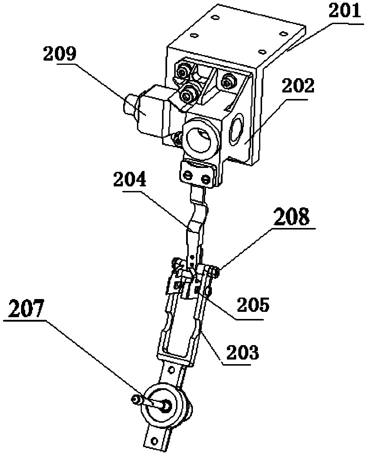
[0023] See attached figure 2 , 6 , the compression release mechanism 2 includes: a mounting seat 201, a compression seat assembly 202, a swing frame 203, a mounting frame 204, a limit pallet 205, a locking reed 206, a compression screw rod 207 and a pyrotechnic cutter 209; The seat assembly 202 is fixedly installed on the mounting seat 201; the middle section of the mounting frame 204 is provided with an arc groove, and the tail is provided with a limit bracket 205, and the limit bracket 205 is fixed with a locking reed 206, and the locking reed 206 has a locking notch; the swing frame 203 is provided with protruding screws, and the middle section of the swing frame 203 is also provided with an arc-shaped groove; the head of the mounting frame 204 is fixedly connected with the pr...


PUM


Abstract

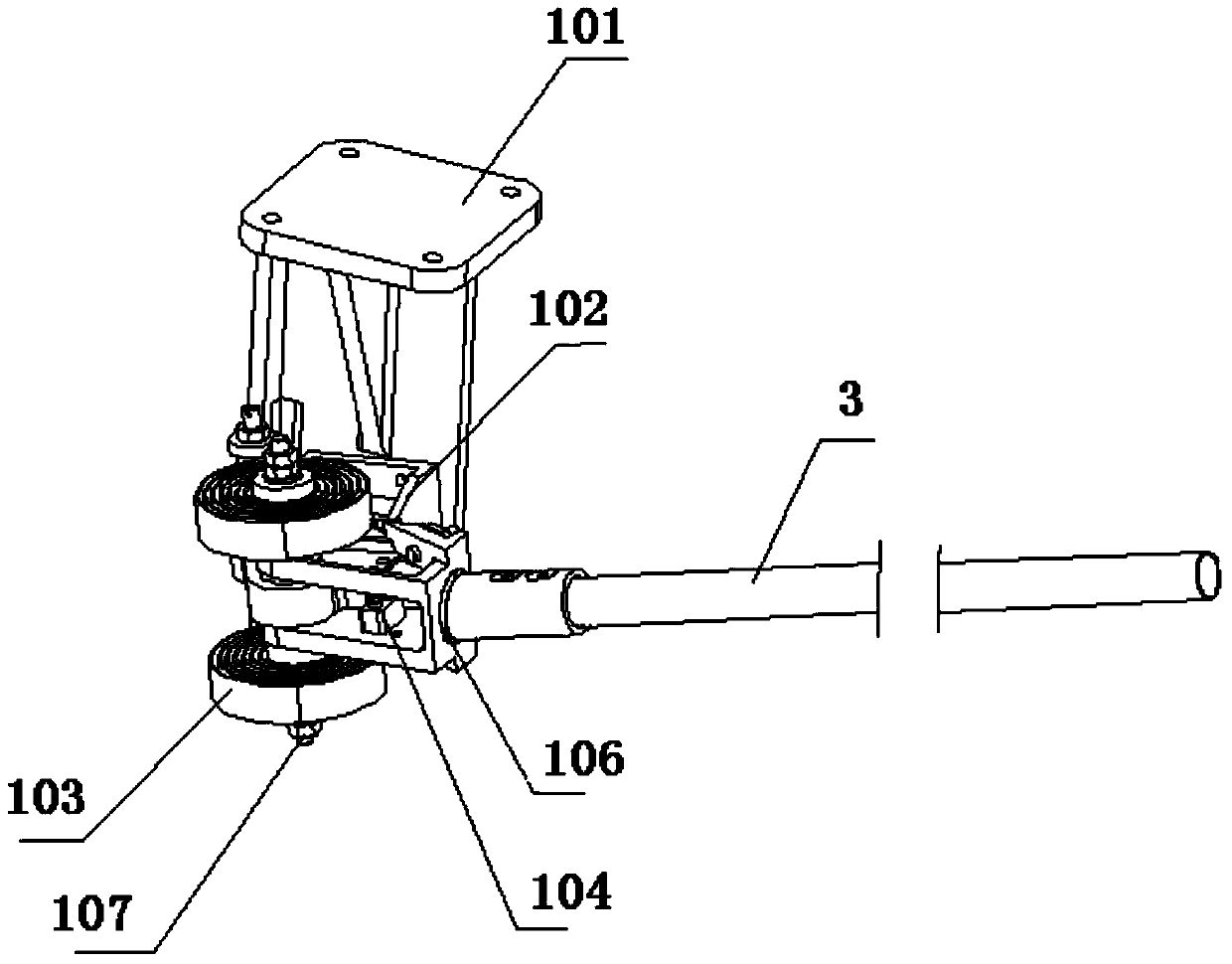
The invention belongs to the technical field of aerospace spaceborne antennas and particularly relates to an unfolding release device of a rod antenna. According to the technical scheme, the unfolding release device comprises the rod antenna (3), a compression release mechanism (2) and an unfolding locking mechanism (1); the compression release mechanism (2) comprises an installation base (201), a compression base assembly (202), a swing frame (203), an installation frame (204), a limiting supporting plate (205), a locking reed (206), a compression screw (207) and a pyrotechnic cutter (209); the unfolding locking mechanism (1) comprises an installation frame (101), a fixed hinge support (102), a volute spring (103), a limiting block (104), a locking leaf spring (105) and a rotating hinged head (106). According to the unfolding release device of the rod antenna, the rod antenna (3) can be unfolded to a fixed angle and can be effectively locked before and after the release.

Description

technical field [0001] The invention belongs to the technical field of aerospace satellite-borne antennas, and in particular relates to a deploying device for a rod-shaped antenna. Background technique [0002] With the rapid development of space technology in recent years, the space deployment technology of spaceborne antennas has been more and more widely used. There are mainly motor drive, air pressure drive, and spring drive to drive the spaceborne antenna deployment device. The motor and air pressure drive have a relatively large additional mass of the mechanism itself, and the structure tends to be complicated, which brings a lot of pressure on the satellite's lightweight and reduces the The reliability of the institution's work. The mechanism is light in weight, simple in structure, reliable in operation, and strong in adaptability to the environment, which is one of the development directions of spaceborne antenna deployment devices. Contents of the invention [...

Claims


Application Information

Patent Timeline
IPC IPC(8): H01Q1/08
Inventor 唐传军刘冬纪奕才方广有李潇周斌卢伟李定坤
Owner INST OF ELECTRONICS CHINESE ACAD OF SCI
Learn More