
Double-fed dual-polarization microstrip antenna

A microstrip antenna, dual-polarization technology, applied in the antenna unit combination, antenna, radiating element structure and other directions with different polarization directions, can solve the problem of affecting the antenna gain, only 13dB and 16dB, affecting the isolation performance, etc.

Active Publication Date: 2014-12-10
XIAMEN UNIV
View PDF4 Cites 4 Cited by
  • Summary
  • Abstract
  • Description
  • Claims
  • Application Information

AI Technical Summary

Problems solved by technology

Literature (Lu J, Kuai Z, Zhu X, et al.A high-isolation dual-polarization microstrip patch antenna with quasi-cross-shaped coupling slot[J].Antennas and Propagation,IEEE Transactions on,2011,59(7) :2713-2717) adopts the dual-polarized patch antenna with quasi-cross slot coupling feed, the isolation is generally better than 40dB in the working frequency band, but there are two peaks in the S21 curve, which seriously affects the isolation in this frequency band performance, and the feed model of this structure is relatively complex; and because of the slot coupling feed, it will radiate to the back of the ground plane, affecting the gain of the antenna
Literature (Yuan D, Du Z, Gong K, et al.A novel dual-band printed diversity antenna for mobile terminals[J].Antennas and Propagation,IEEE Transactions on,2007,55(7):2088-2096) Introduction 1 A dual-frequency dual-polarized antenna composed of two back-facing monopoles printed on a circuit board is applied to a polarized antenna capable of dual-frequency operation on a mobile terminal, but its isolation is different in the two frequency bands. Only 13dB and 16dB

Method used


Image

  • Double-fed dual-polarization microstrip antenna
  • Double-fed dual-polarization microstrip antenna
  • Double-fed dual-polarization microstrip antenna

Examples


Embodiment Construction

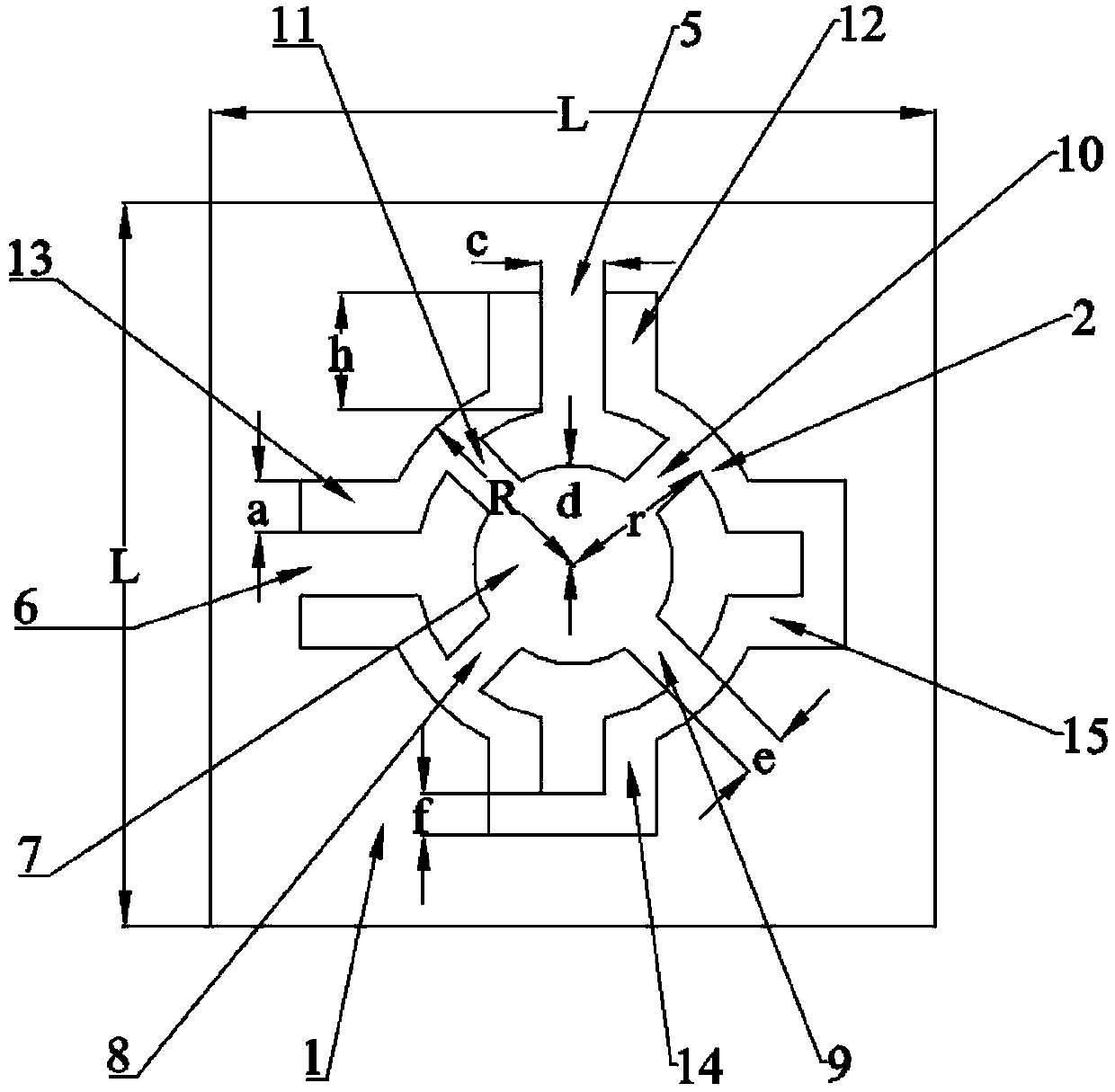
[0021] see figure 1 , this embodiment is provided with a dielectric substrate 1 and a radiation patch; the radiation patch is arranged on the front of the dielectric substrate 1, the geometric center of the radiation patch coincides with the geometric center of the dielectric substrate 1, and the back of the dielectric substrate 1 is grounded. The pattern of the radiation patch is gear-shaped, and the radiation patch is provided with a central disc 7, 4 identical concentric circular arcs 2, 4 identical spokes 8, 9, 10 and 11, and 4 teeth 14, 15 , 12 and 13. Taking the central disc 7 as a benchmark, four concentric arcs 2 and four spokes 8, 9, 10 and 11 are symmetrically arranged on the periphery of the central disc 7, and each concentric arc 2 passes through a spoke and The central disc 7 is connected. The 4 teeth are evenly distributed and orthogonally located at the four ends of the radiation patch, up, down, left, and right, and are arranged at both ends of each concentri...


PUM


Abstract

The invention relates to a patch antenna, in particular to a double-fed dual-polarization microstrip antenna. The double-fed dual-polarization microstrip antenna comprises a dielectric substrate and a radiation patch arranged on the front face of the dielectric substrate, a geometric center of the radiation patch is coincided with that of the dielectric substrate 1, and the back face of the dielectric substrate is grounded. The radiation patch is in a shape of a toothed gear and comprises a central circular piece, four identical concentric arc pieces, four identical radial strip pieces and four teeth; the four concentric arc pieces and the four identical radial strip pieces are symmetrically arranged on the outer periphery of the central circular piece, and each concentric arc piece is connected with the central circular piece through one radial strip piece; the four teeth are uniformly distributed and orthogonally positioned at four ends of the radiation patch and are arranged at two ends of each concentric arc piece, two adjacent teeth of the four teeth are identical U-shaped teeth, and the other two adjacent teeth are identical broken teeth which are U-shaped teeth with radial middle openings serving as feed ports. The double-fed dual-polarization microstrip antenna is high in isolation and has excellent dual polarization characteristics.

Description

technical field [0001] The invention relates to a patch antenna, in particular to a double-fed double-polarized microstrip antenna with high isolation of unidirectional radiation fed by slot lines. Background technique [0002] With the rapid development of modern digital multimedia technology, human beings have an increasing demand for the transmission of images, audio, video and other media in daily mobile communications. 4G network communication is an emerging technology. Compared with traditional communication technologies, the transmission rate can reach 100Mbit / s, and it can ensure the stability and security of transmission. Therefore, the 4G network has attracted the attention of more and more users. TD-LTE technology, one of the technical labels of 4G network, its key technology is MIMO (Multi-InputMulti-Output) technology. MIMO technology utilizes the space-time processing technology of the multi-antenna system to transmit multiple pieces of data at the same time,...

Claims


Application Information

Patent Timeline
Patent Type & Authority Applications(China)
IPC IPC(8): H01Q1/38H01Q13/08H01Q21/24
Inventor 李伟文王琛张斌张志悦陈晓建游佰强徐伟明
Owner XIAMEN UNIV
Learn More