A Dual Polarization CTS Beam Scanning Antenna Array

A beam scanning, dual-polarization technology, applied in the combination of antenna units with different polarization directions, the structure of radiating elements, etc., can solve the problems that mechanical scanning antennas and phased array antennas are difficult to meet, and achieve good dual-polarization characteristics. , Large beam scanning range, the effect of solving beam scanning problems

Active Publication Date: 2020-08-04
SHANGHAI UNIV
View PDF5 Cites 0 Cited by
  • Summary
  • Abstract
  • Description
  • Claims
  • Application Information

AI Technical Summary

Problems solved by technology

Both mechanical scanning antennas and phased array antennas are difficult to meet this requirement

Method used


Image

  • A Dual Polarization CTS Beam Scanning Antenna Array
  • A Dual Polarization CTS Beam Scanning Antenna Array
  • A Dual Polarization CTS Beam Scanning Antenna Array

Examples


Embodiment Construction

[0021] A preferred example of the present invention is described in detail as follows in conjunction with accompanying drawing:

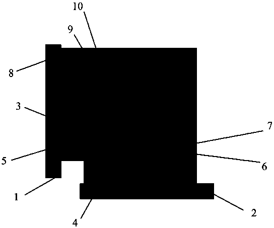
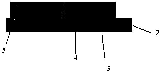
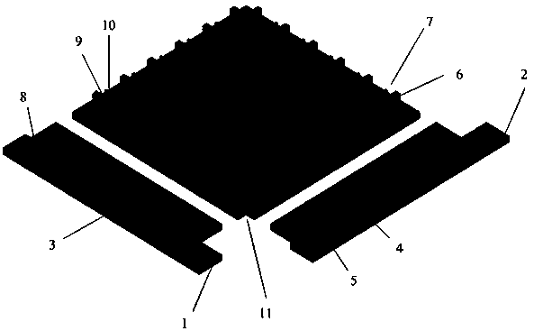
[0022] Such as Figure 1 to Figure 4 As shown, a dual-polarized CTS beam scanning antenna array includes two orthogonal waveguide power-splitting feed structures and a dual-polarized CTS antenna array; the waveguide power-splitting structure is connected to the side of the CTS antenna array to generate plane waves, The dual-polarized CTS antenna array realizes H-plane scanning as frequency changes.

[0023] Each waveguide power divider feed structure includes a feed port, four sequentially connected one-to-two waveguide power dividers, and an inductive metal wall 8; one end of the waveguide power divider feed structure is a horizontal feed port 1 or a vertical The feed port 2 is provided with an inductive metal wall 8 at the other end; each power divider includes a metal column 3, a first coupling window 4, and a second coupling window 5, wherein t...


PUM

PropertyMeasurementUnit
isolationaaaaaaaaaa

Abstract

The invention relates to a dual-polarization CTS (Continuous Transverse Stub) beam scanning antenna array. The dual-polarization CTS beam scanning antenna array comprises two orthogonal waveguide power distribution feed structures and a dual-polarization CTS antenna array, wherein the waveguide power distribution structures are connected to the side surface of the CTS antenna array and are used for generating a plane wave; the dual-polarization CTS antenna array achieves H-side scanning along with frequency change. The antenna array achieves H-side beam scanning through the change of the frequency at a port, and can achieve beam scanning of -22 degrees to 9 degrees in the change range of 5.1.6-12.8GHz.

Description

technical field [0001] The invention relates to the field of beam scanning antennas, in particular to a dual-polarization CTS beam scanning antenna array for realizing beam scanning of dual-polarization antennas. Background technique [0002] With the development of wireless communication technology, there is an increasing demand for antennas to perform high-speed communication anytime and anywhere on mobile carriers, and broadband beam scanning antenna arrays have received extensive attention. The beam scanning antenna has the performance of high gain, high directivity, and controllable beam pointing. By changing the working mode, working state, working frequency or antenna posture of the antenna, the maximum radiation direction of the antenna can be changed, thereby realizing beam scanning. At present, in terms of mobile communication networks, the use of this high-gain antenna technology with variable radiation direction can meet the high-speed communication needs of use...

Claims


Application Information

Patent Timeline
Patent Type & Authority Patents(China)
IPC IPC(8): H01Q1/36H01Q21/24
CPCH01Q1/36H01Q21/24
Inventor 杨雪霞邱厚童楼天彭章飞朱乃达
Owner SHANGHAI UNIV
Why Eureka
Try Eureka