Loop antenna
A loop antenna and antenna technology, applied in the field of antennas, can solve the problems of inapplicability to passive communication, large impedance, communication limitations, etc., and achieve the effects of not being able to drastically reduce the gain, reducing impedance, and improving efficiency.
- Summary
- Abstract
- Description
- Claims
- Application Information
AI Technical Summary
Problems solved by technology
Method used
Image

Examples
Embodiment Construction
[0020] In order to better illustrate the technical characteristics and structure of the present invention, the following is a detailed description in conjunction with preferred embodiments of the present invention and accompanying drawings.
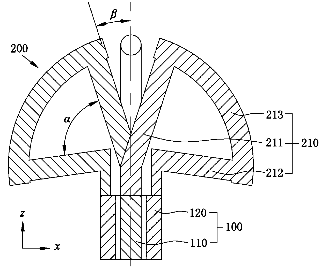
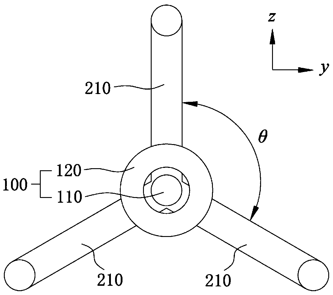
[0021] refer to figure 1 and figure 2 , the loop antenna provided by the present invention includes a feeder 100 and an antenna body 200, wherein the feeder 110 is provided with a feeder positive pole 110 and a feeder negative pole 120, the feeder positive pole 110 and the feeder negative pole 120 are coaxial, the feeder positive pole 110 is located inside the feeder line 100, and the feeder line The negative electrode 120 is a surrounding dielectric surrounding the positive electrode 110 of the feeder line, and forms the feeder line 100 with the positive electrode 110 of the feeder line. The antenna body 200 includes a plurality of antenna units 210 in a ring structure, and the plurality of antenna units 210 are symmetrically distribut...
PUM
| Property | Measurement | Unit |
|---|---|---|
| Angle | aaaaa | aaaaa |
Abstract
Description
Claims
Application Information
PatSnap Eureka turns technology decisions into work you can execute. Powered by our Innovation Knowledge Graph, it runs expert workflows across engineering, life sciences, materials and intellectual property. Get your review-ready output in minutes.


