Stator and rotor punching sheet production line

A stator-rotor and production line technology, which is applied in the manufacture of stator/rotor body, etc., can solve the problems of difficult rotor and fragment separation, imperfect screening device, high manual operation intensity, etc., and achieve the goals of ensuring safety and reliability, moving conveniently, and improving efficiency Effect

Active Publication Date: 2014-12-10
LUAN MICRO & SPECIAL MOTOR
View PDF8 Cites 5 Cited by
  • Summary
  • Abstract
  • Description
  • Claims
  • Application Information

AI Technical Summary

Problems solved by technology

At the same time, the screening device is not perfect, and it is difficult to separate stators, rotors and debris of different sizes
This technology has the disadvantages of low efficiency, high manual operation intensity and high cost.

Method used


Image

  • Stator and rotor punching sheet production line
  • Stator and rotor punching sheet production line
  • Stator and rotor punching sheet production line

Examples


Embodiment Construction

[0047] The following will clearly and completely describe the technical solutions in the embodiments of the present invention with reference to the accompanying drawings in the embodiments of the present invention. Obviously, the described embodiments are only some, not all, embodiments of the present invention. Based on the embodiments of the present invention, all other embodiments obtained by persons of ordinary skill in the art without making creative efforts belong to the protection scope of the present invention.

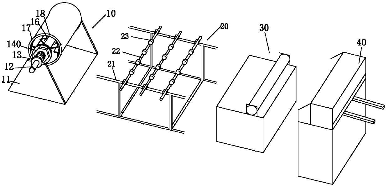
[0048] Such as figure 1As shown, a stator and rotor stamping production line includes a cutting system for cutting silicon steel coils into blanking plates, and a stamping device for stamping blanking plates into stator and rotor stampings. The stamping outlet of the stamping device A screening device 60 is placed obliquely, and the higher end of the screening device 60 is located at the punching outlet of the stamping device; Sorting device;

[0049] The cu...


PUM


Abstract

The invention belongs to the motor manufacture technology field, and relates to a stator and rotor punching sheet production line. The stator and rotor punching sheet production line comprises a clipping system used to clip a silicon steel coil into blanking plates and a punching device used to punch the blanking plates into stator and rotor punching sheets, wherein a screening device is obliquely arranged on a punching sheet outlet of the punching device, and one end of the screening device, which is higher than the other end of the screening device, is located on the punching sheet outlet of the punching device. The stator and rotor punching sheet production line further comprises a sorting device used to sort the stator and rotor punching sheets which fall onto the ground. The stator and rotor punching sheet production line improves production efficiency, saves labor, and thereby saves cost.

Description

technical field [0001] The invention belongs to the technical field of motor manufacturing, and relates to a stator and rotor sheet punching production line. Background technique [0002] In the process of making the motor, the stator and the rotor are formed by superimposing and pressing stamped sheets. The silicon steel sheets used for stator and rotor punching are produced into large coils of about 1200-1250MM according to the specifications when they leave the factory. When the motor stator and rotor stamping factory stamps into punching sheets, due to the limitation of the tonnage of the mold and punching machine, the material needs to be cut into a set shape according to the single-row or double-row production of the motor stator and rotor and the overlap of 1.5-2MM before stamping blanking board. [0003] When the stamping device stamps the blanking plate into stator and rotor punches of different sizes, the stator and rotor punches of different sizes are mixed toge...

Claims


Application Information

Patent Timeline
Patent Type & Authority Applications(China)
IPC IPC(8): H02K15/02
CPCH02K15/02
Inventor 段志诚段照仁晁明男陈明生周伟方俊
Owner LUAN MICRO & SPECIAL MOTOR
Why Eureka
Try Eureka