Optical coherence tomography apparatus and optical coherence tomography method
A technology of optical coherence tomography and imaging equipment, which is applied in the direction of material analysis through optical means, the use of optical devices, scientific instruments, etc., and can solve problems such as no discussion
- Summary
- Abstract
- Description
- Claims
- Application Information
AI Technical Summary
Problems solved by technology
Method used
Image
Examples
no. 1 example
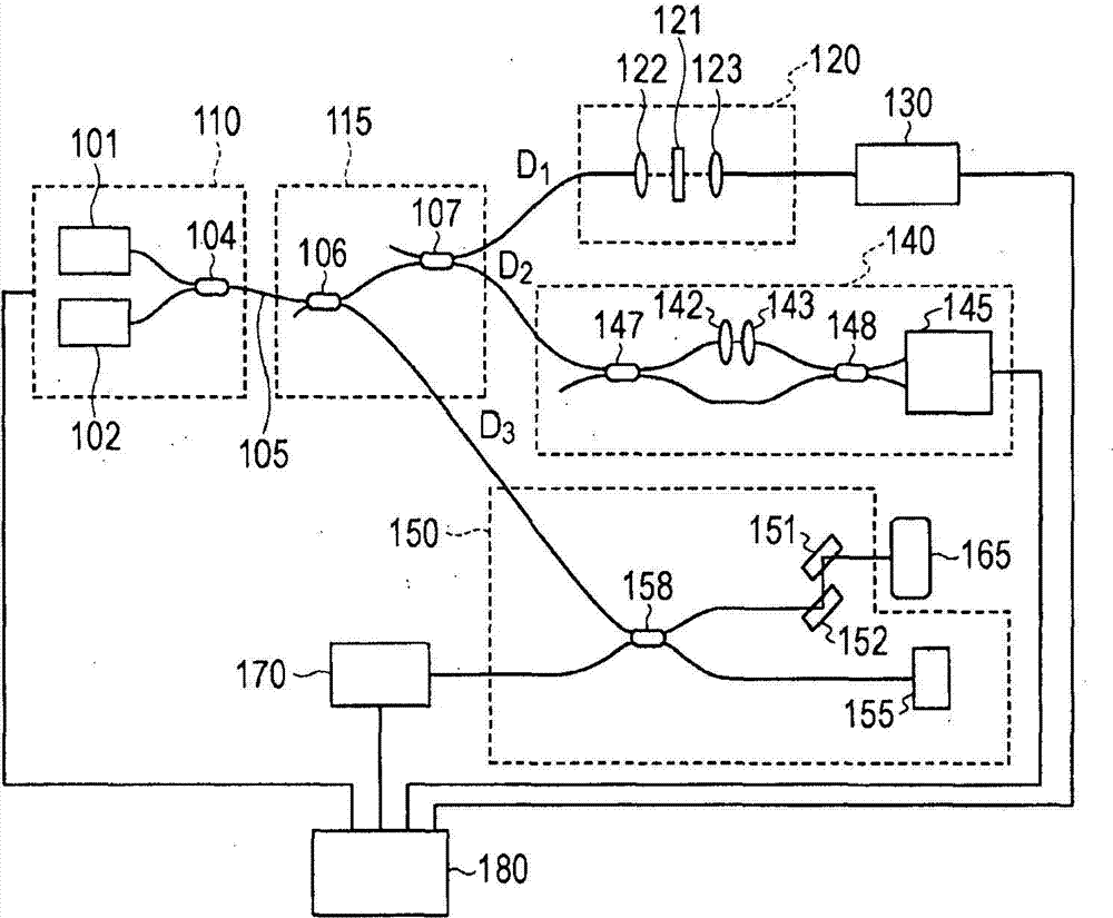
[0114] image 3 is a schematic diagram showing the optical coherence tomography apparatus according to the first embodiment. In the device according to the present embodiment, two wavenumber clock interferometers are provided to reduce the required wavelength detection accuracy.
[0115] light source unit
[0116]The light source unit emits light obtained by combining light emitted from two swept light sources 301 and 302 each emitting light having an oscillation wavelength that changes periodically using a fiber coupler 303 .
[0117] The frequency-swept light source 301 transmits a synchronization signal 333 to a PC 340 included in the processing unit. The synchronization signal 333 allows the A / D board to start acquiring data in synchronization with the periodic variation of the oscillation wavelength.
[0118] Each swept light source is a light source that emits light obtained by filtering light spatially extended by the diffraction grating by moving a slit-like mirror....
no. 2 example
[0156] Figure 4 is a schematic diagram showing an optical coherence tomography apparatus according to a second embodiment.
[0157] light source unit
[0158] The light source unit and the OCT interferometer according to the present embodiment have structures similar to those of the first embodiment. exist Figure 4 in, with image 3 Components similar to those shown in are denoted by the same reference numerals, and their explanations will be omitted to avoid redundancy.
[0159] OCT interferometer and generation of interferometric signals
[0160] Light obtained by combining the lights emitted from the two swept light sources 301 and 302 is emitted from the light source unit, and is split into two lights by the fiber coupler 403 . One of the two lights that have been separated from each other is guided to an OCT interferometer. Spectral interference signal 339 is obtained by an OCT interferometer and input to PC 340 .
[0161] Detection of time to output a predetermi...
no. 3 example
[0182] An optical coherence tomography apparatus according to a third embodiment includes a light source unit including three swept light sources. will refer to Figure 5 The optical coherence tomography apparatus is described.
[0183] light source unit
[0184] The light source unit emits light obtained by combining light emitted from three frequency-sweeping light sources 501, 502, and 503 each emitting light having an oscillation wavelength that changes periodically by using an optical combiner 504 .
[0185] Each swept light source is a light source that emits light obtained by filtering light spatially extended by the diffraction grating by moving a slit-like mirror.
[0186] The output spectral ranges of the three frequency-sweeping light sources 501, 502, and 503 are 800 to 835 nm, 825 to 860 nm, and 850 to 885 nm, respectively, and each of the frequency-sweeping light sources sweeps the wavelength from the short-wavelength side to the long-wavelength side within 3 ...
PUM
 Abstract
Description
Claims
Application Information
 - R&D Engineer
- R&D Manager
- IP Professional
- Industry Leading Data Capabilities
- Powerful AI technology
- Patent DNA Extraction
Browse by: Latest US Patents, China's latest patents, Technical Efficacy Thesaurus, Application Domain, Technology Topic.
© 2024 PatSnap. All rights reserved.Legal|Privacy policy|Modern Slavery Act Transparency Statement|Sitemap


