Disassembly and assembly structure for furniture drawer front panel

A front panel and drawer technology, which is applied to drawers, furniture parts, household appliances, etc., can solve the problems of inconvenient daily use of drawer panels, inconvenient use by users, and unsatisfactory users, and reduce assembly steps. And the effect of manufacturing tolerance, quick disassembly and assembly, great flexibility

Active Publication Date: 2014-12-17
伍志勇
View PDF7 Cites 11 Cited by
  • Summary
  • Abstract
  • Description
  • Claims
  • Application Information

AI Technical Summary

Problems solved by technology

When the height of the panel of the drawer in this structure is relatively high, it is extremely easy to shake, which makes the user unsatisfied; and the connecting piece on the panel needs to be connected with the ...

Method used


Image

  • Disassembly and assembly structure for furniture drawer front panel
  • Disassembly and assembly structure for furniture drawer front panel
  • Disassembly and assembly structure for furniture drawer front panel

Examples


no. 1 example

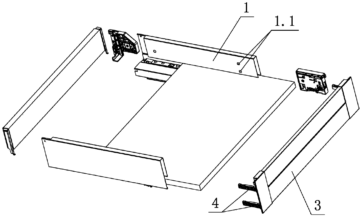
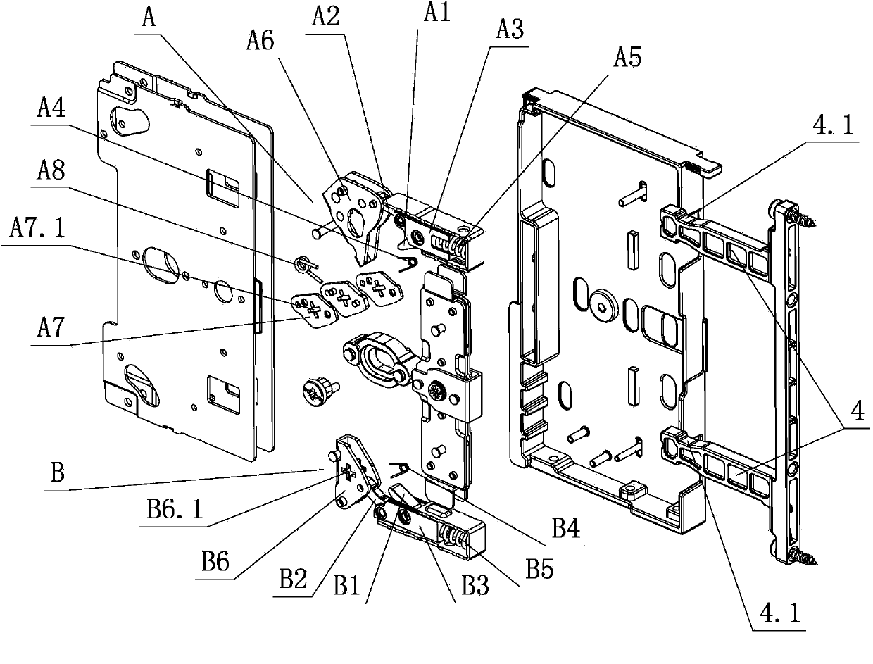
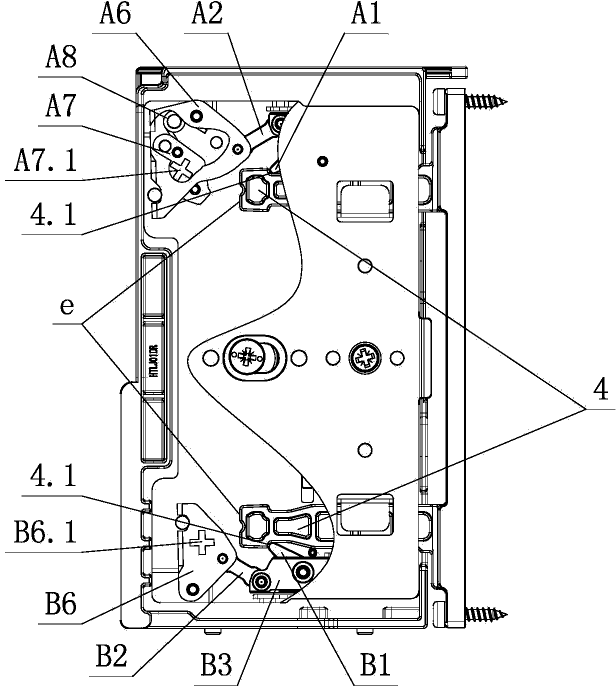
[0026] see Figure 1-Figure 14, the disassembly and assembly structure of the front panel of the furniture drawer includes a fixing device arranged on the side panel 1, the front panel 3 is connected with the fixing device through more than two connecting elements 4, and more than two sets of locking devices are arranged on the fixing device. Locking and separating the lock-off mechanism of the connecting element 4, the two or more sets of lock-off mechanisms are relatively independent up and down; wherein, at least one set of the first lock-off mechanism A and the connecting element 4 are unlocked and / or after unlocking, The front and rear positions of the connecting element 4 on the first lock-off mechanism A remain basically unchanged, or can move within the effective range d and are no longer locked; when the second lock-off mechanism B and the connecting element 4 are unlocked, the second lock-off mechanism B The push-out element B6 of the mechanism B pushes the connectin...

no. 2 example

[0043] see Figure 15 , Figure 16 , the dismounting structure of the front panel of the furniture drawer is different from the first embodiment in that: the fixing device is provided with a release element 2, and the release element 2 is provided with a release function part 2.1 for a tool, and the release element 2 Respectively through the interlocking element 5 and / or the ejection element 6, it is drivingly connected with the holding element A7 and the ejection element B6, and acts on the release part 2.1 of the release element 2 through a tool, and is driven and held by the interlocking element 5 and / or the ejection element 6 The element A7 and the push-out element B6 swing, and the connecting element 4 is unlocked synchronously with the first lock-off mechanism A and the second lock-off mechanism B through the release part 2.1.

[0044] Others are not described in the first embodiment.


PUM


Abstract

The invention relates to a disassembly and assembly structure for a furniture drawer front panel. The disassembly and assembly structure comprises a fixing device arranged on a side plate, wherein the front panel is connected with the fixing device through more than two connecting elements, and more than two sets of locking and separating mechanisms for locking and separating the connecting elements are arranged on the fixing device and are independently arranged up and down; when and/or after at least one set of first locking and separating mechanisms and the connecting elements are unlocked, the front and back positions of the connecting elements on the first locking and separating mechanism basically remain unchanged, or can move in an effective range and are not be locked any more; when a second locking and separating mechanism and the connecting elements are unlocked, a pushing-out element of the second locking and separating mechanism pushes the locking positions of the connecting elements in the second locking and separating mechanism for a stroke to unlock. The disassembly and assembly structure provided by the invention has the characteristics of simple and reasonable structure, reliable performance, reliable connection, low manufacturing cost, quick and convenient disassembly and assembly, high flexibility, wide range of use and the like, and has high practicality.

Description

technical field [0001] The invention relates to a front panel of a furniture drawer, in particular to a disassembly structure for the front panel of a furniture drawer. Background technique [0002] Chinese Patent Document No. CN 101224065A disclosed a panel locking and adjusting device for a drawer with slide rails on July 23, 2008. There is a guide groove in the adjustment seat for the sliding of the connecting piece, and a panel locking mechanism is arranged in the guide groove. The panel locking mechanism includes an eccentric cam arranged on the adjustment seat, the other end of which is hinged with the guide block through a connecting rod, and the swing rod One end is hinged on the guide block through the pin shaft, the torsion spring is sleeved on the pin shaft, one end is connected to the swing rod, the other end is connected to the guide block or the adjustment seat, the guide block is slidingly sleeved in the adjustment seat, and connected The end of the piece is ...

Claims


Application Information

Patent Timeline
IPC IPC(8): A47B88/00
Inventor 伍志勇
Owner 伍志勇
Why Eureka
Try Eureka