
Activated carbon jetting device

A technology of injection device and activated carbon, which is applied in the direction of injection device, injection device, dispersed particle separation, etc., can solve the problems that activated carbon cannot completely cover the flue, the diffusion effect of the direct injection port is not very good, and dioxin enters the external air, etc. Achieve the effect of small resistance, reduce resistance and protect the external environment

Inactive Publication Date: 2014-12-17
WUXI XUELANG ENVIRONMENTAL TECH CO LTD
View PDF5 Cites 6 Cited by
  • Summary
  • Abstract
  • Description
  • Claims
  • Application Information

AI Technical Summary

Problems solved by technology

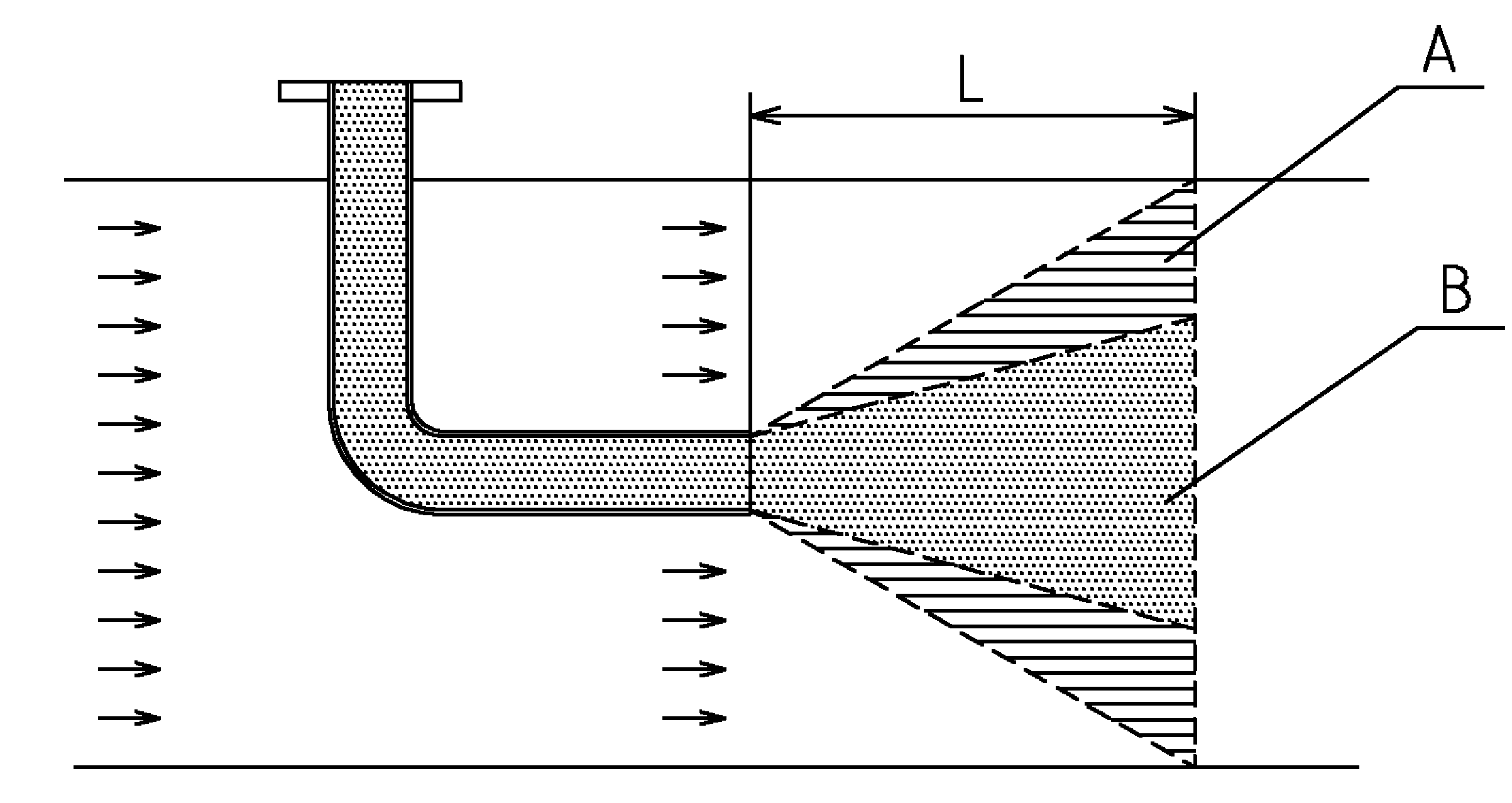
[0004] Existing activated carbon injection device, see figure 1 , using a straight pipe directly inserted into the flue, the nozzle of the injection device is a straight nozzle, the diffusion effect of the straight nozzle is not very good, so the injected activated carbon cannot completely cover the flow surface of the flue
In the figure, A is the activated carbon diffusion area sprayed into the flue, and B is the active area that is not covered. Due to the small diffusion angle of the straight nozzle and the low jet velocity, the concentration in the middle of the sprayed diffusion area is higher, and the concentration in the edge area is higher. Low, the activated carbon diffusion stroke L is not enough to make the activated carbon cover all the flow surfaces in the flue gas conveying direction, so that the dioxins in the flue gas cannot fully contact with the activated carbon, the absorption rate of dioxins is low, and it is easy for dioxins to enter the external air in, damage the environment

Method used


Image

  • Activated carbon jetting device
  • Activated carbon jetting device
  • Activated carbon jetting device

Examples


Embodiment Construction

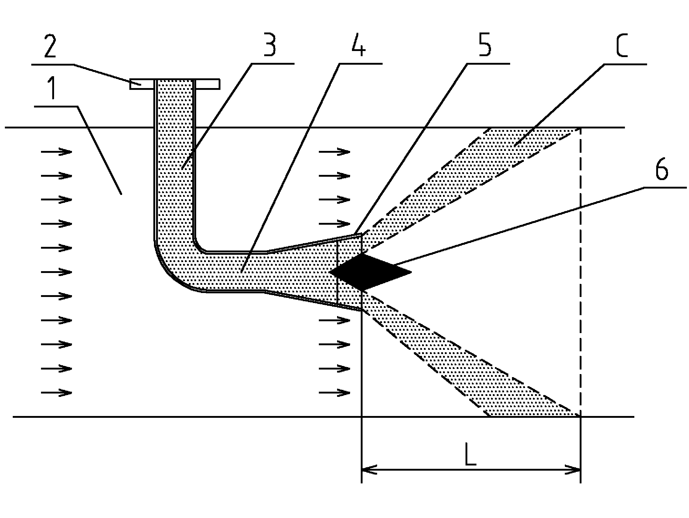
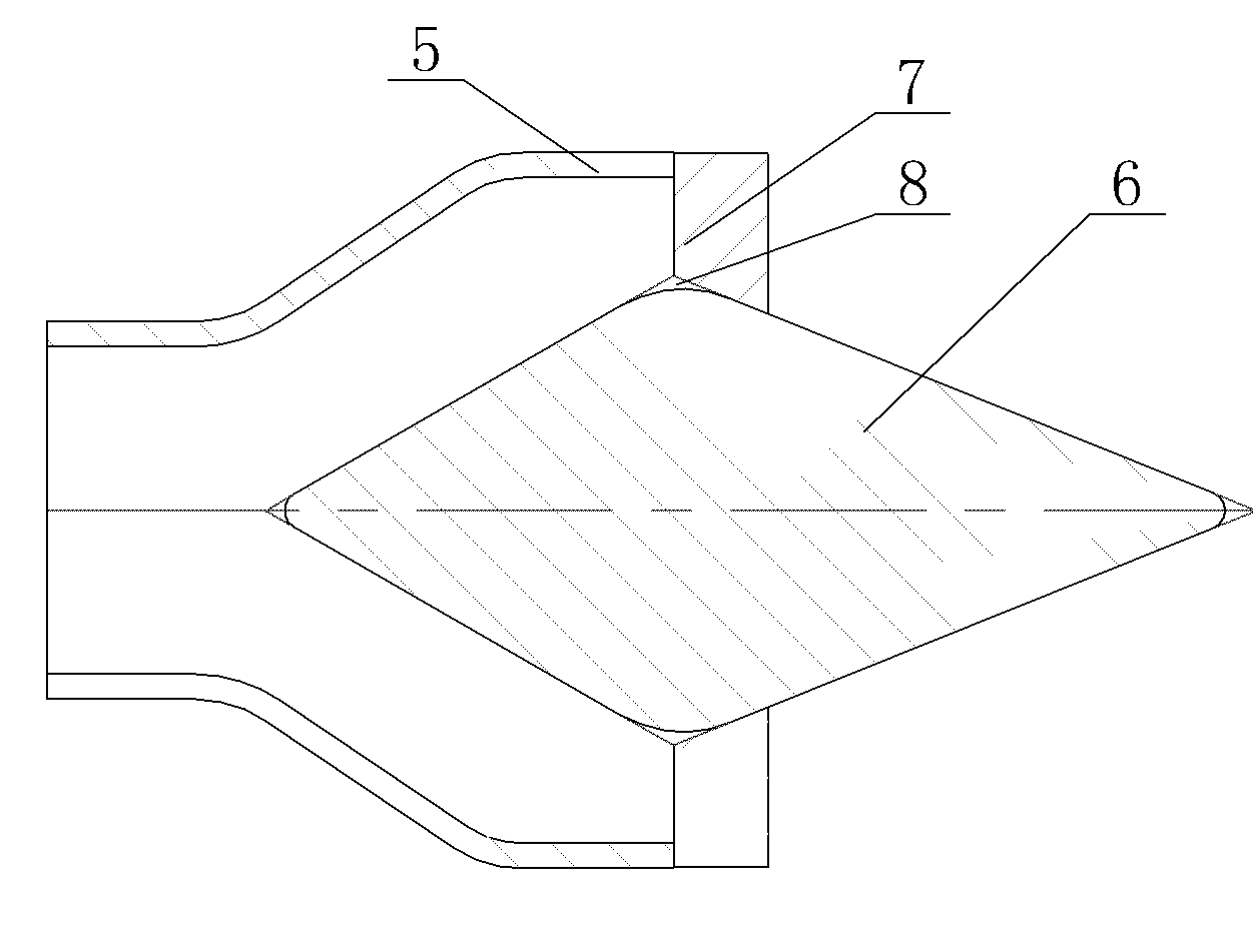
[0017] An activated carbon injection device, see Figure 2 ~ Figure 4 : It includes a flue 1, in which flue gas circulates, an activated carbon injection pipe is arranged in the flue 1, and the flue gas is exhausted from front to back along the flue 1, and the activated carbon injection pipe It includes a feed port 2, a vertical connecting pipe 3, and a horizontal outlet pipe 4 exposed at the upper end of the pipe. The outlet 5 of the horizontal outlet pipe 4 is a flared trumpet shape. The inlet of the oriented outlet pipe 4 is connected to the lower outlet of the vertical connecting pipe 3, the horizontal outlet pipe 4 is arranged along the direction of flue gas outlet, and the outlet 5 of the horizontal outlet pipe 4 is arranged with increasing For the speed cone 6, the front end of the speed increasing cone 6 is a cone structure, and the cone structure is a cone that flares from front to back.

[0018] The rear end portion of the speed increasing cone 6 is a tapered structure...


PUM


Abstract

The invention provides an activated carbon jetting device. Activated carbon in a flue can cover all flowing surfaces conveyed by a flue gas, the concentration of an activated carbon diffusion area is uniform to ensure that dioxin in flue gas can be fully contacted with activated carbon, so that the absorption rate of dioxin is high, dioxin does not easily enter external air and thus an external environment is protected. The activated carbon jetting device comprises a flue, the flue gas flows in the flue, an activated carbon jetting pipeline is distributed in the flue, the flue gas is exhausted from front to rear along the flue; the activated carbon jetting device is characterized in that the activated carbon jetting pipeline comprises a feed inlet, a vertical connecting pipeline and a horizontal outlet pipeline, wherein the feed inlet is exposed outside the upper end of the pipeline, an outlet of the horizontal outlet pipeline is an outward flared horn, an inlet of the horizontal outlet pipeline is connected with an outlet in the lower part of the vertical connecting pipeline, and the horizontal outlet pipeline is distributed along the outlet direction of the flue gas.

Description

Technical field [0001] The invention relates to the technical field of waste incineration tail gas structures, in particular to an activated carbon injection device. Background technique [0002] Dioxin refers to a chlorine-containing organic compound that contains two or one oxygen bond connecting two benzene rings. Its English name is "Dioxin". Due to the different substitution positions of Cl atoms at 1-9, they constitute 75 isomers of polychlorinated diphenyls (PCDD) and 135 isomers of polychlorinated dibenzofurans (PCDF), usually collectively referred to as dioxins. The molecular weight is 321.96, it is white crystal, mp: 302~305℃, decomposes at 500℃, and completely decomposes at 800℃ in 21s. Among them, 17 species (positions 2, 3, 7, and 8 replaced by Cl) are considered to be the most serious to humans and biological hazards. Dioxins are stable in nature, with a half-life of 12a in soil and 8.3d of photochemical decomposition of gaseous dioxins in the air. They are slowly...

Claims


Application Information

Patent Timeline
Patent Type & Authority Applications(China)
IPC IPC(8): B01D53/10B05B1/06
Inventor 虞大青
Owner WUXI XUELANG ENVIRONMENTAL TECH CO LTD
Learn More