
Single-edge spiral milling cutter

A technology of helical milling cutter and cutter body, applied in milling cutters, milling machine equipment, manufacturing tools, etc., can solve the problems of reduced milling force and precision, small chip flute depth, and easy slippage.

Inactive Publication Date: 2014-12-17
常州聚美精密工具有限公司
View PDF0 Cites 0 Cited by
  • Summary
  • Abstract
  • Description
  • Claims
  • Application Information

AI Technical Summary

Problems solved by technology

[0002] Many kinds of milling cutters are used in the mechanical processing industry. Most of the existing milling cutters have multiple chip removal grooves, resulting in the depth of the chip removal grooves being too small and not easy to discharge waste chips, which affects the processing quality, and the milling cutter works Slipping is prone to occur during the process, which reduces the strength and precision of milling

Method used


Image

  • Single-edge spiral milling cutter
  • Single-edge spiral milling cutter
  • Single-edge spiral milling cutter

Examples


Embodiment Construction

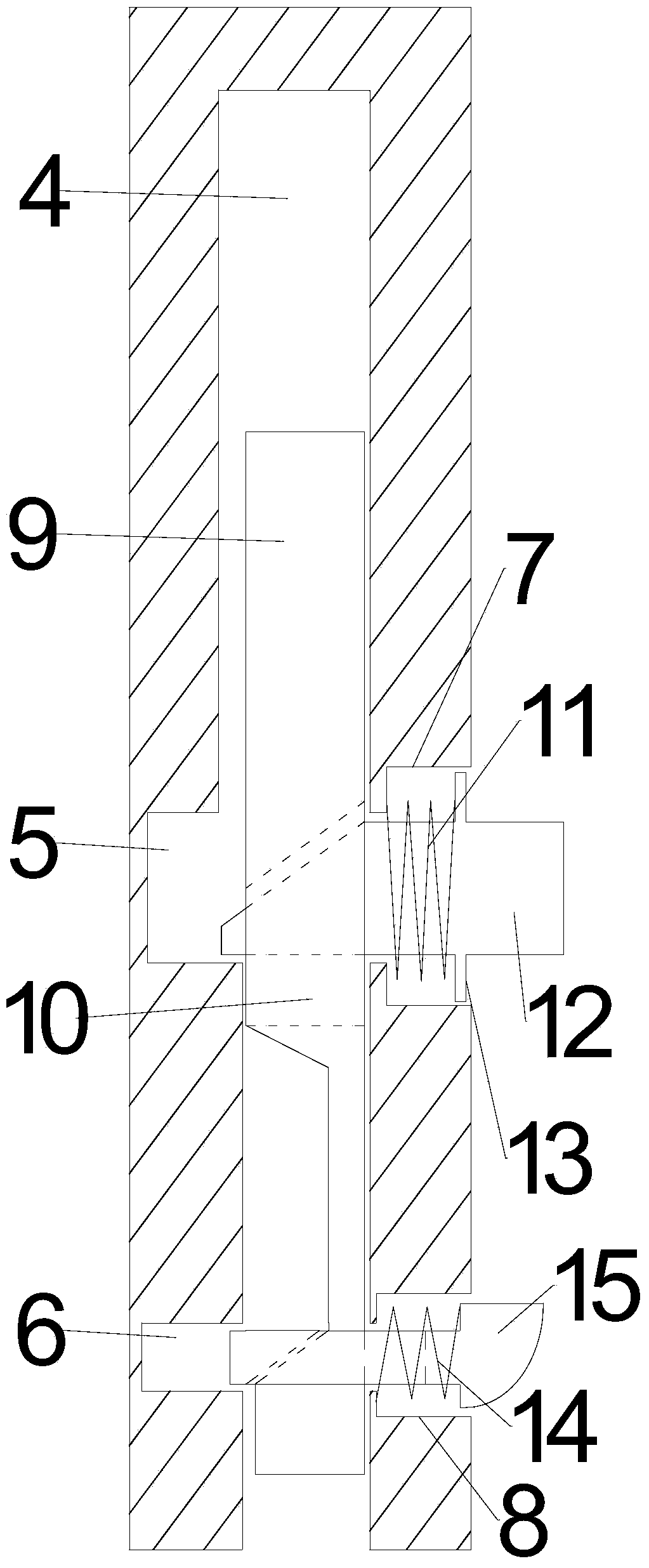
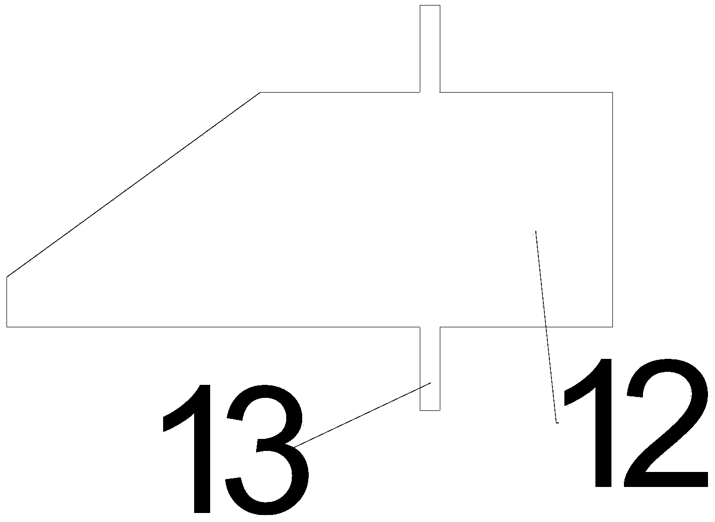
[0017] by Figure 1 to Figure 6 It can be seen that a single-edged helical milling cutter of the present invention includes a tool holder and a tool body. The tool body is provided with an end edge 1, a side cutting edge 2 and a chip flute 3, and the end edge 1 is arranged at the top of the tool body. The side cutting edge 2 and the chip flute 3 spirally extend from the connection between the tool body and the tool holder to the end edge 1, the helix angle of the chip flute 3 is 65°, and the end edge 1 is crescent-shaped, so The tool handle is provided with a cavity 4, an upper guide hole 5, a lower guide hole 6, an upper spring groove 7 and a lower spring groove 8. The upper guide hole 5 communicates with the cavity 4, and the lower guide hole 6 is connected to the cavity 4 is connected, the upper spring groove 7 communicates with the upper guide hole 5, the lower spring groove 8 communicates with the lower guide hole 6, a connecting rod 9 is provided in the cavity 4, and an u...


PUM


Abstract

The invention relates to a single-edge spiral milling cutter. The single-edge spiral milling cutter comprises a shank and a cutter body, wherein the cutter body is provided with an end edge, a side cutting edge and a chip removing groove; the end edge is arranged at the top end of the cutter body; the side cutting edge and the chip removing groove spirally extend to the end edge from the connected place of the cutter body and the shank; the spiral angle of the chip removing groove is 65 degrees; the end edge is crescent; and the shank is provided with a cavity, an upper guide hole, a lower guide hole, an upper spring groove, a lower spring groove, a connecting rod, a push rod and a positioning block. The single-edge spiral milling cutter has the advantages of reasonable structure, high depth of the chip removing groove, reasonable spiral angle and high discharge effect; after the milling cutter is mounted on a machine chuck, a positioning block is arranged for preventing slipping; and when the milling cutter is taken down from the machine chuck, the push rod is pressed to drive the positioning block to shrink in to the lower spring groove through the connecting rod, so that the milling cutter can be conveniently taken down.

Description

Technical field [0001] The invention relates to a milling cutter, especially a single-edged helical milling cutter. Background technique [0002] Many types of milling cutters are used in the machining industry. Most of the existing milling cutters are equipped with multiple chip flutes, which results in too small depth of the chip flutes and it is difficult to discharge waste chips, which affects the quality of processing and the work of the milling cutter. In the process, slipping is easy to occur, which reduces the strength and precision of milling. Summary of the invention [0003] The purpose of the present invention is to provide a single-edged spiral milling cutter with high chip removal efficiency and not easy to slip. [0004] The technical solutions to achieve the purpose of the present invention are as follows: [0005] A single-edged helical milling cutter includes a tool holder and a tool body. The tool body is provided with an end edge, a side cutting edge, and a chip ...

Claims


Application Information

Patent Timeline
IPC IPC(8): B23C5/26B23C5/10
Inventor 恽益群
Owner 常州聚美精密工具有限公司
Learn More