Cutting machine

A cutting machine, sticky technology, applied in the field of cutting machines, can solve the problems of high cost, increased wear, difficult cost, etc.

Active Publication Date: 2014-12-17
KARL EUGEN FISCHER GMBH
View PDF4 Cites 4 Cited by
  • Summary
  • Abstract
  • Description
  • Claims
  • Application Information

AI Technical Summary

Problems solved by technology

However, it has been found that due to the material elasticity of the crank arm, the bearing is subjected to relatively high loads, which leads to increased wear
In addition, this leads, in particular in the case of stronger bands, to the fact that the crank arm has to be manufactured relatively stable, ie with high material outlay, which is difficult and expensive to produce a precise cut section.

Method used


Image

  • Cutting machine
  • Cutting machine
  • Cutting machine

Examples


Embodiment Construction

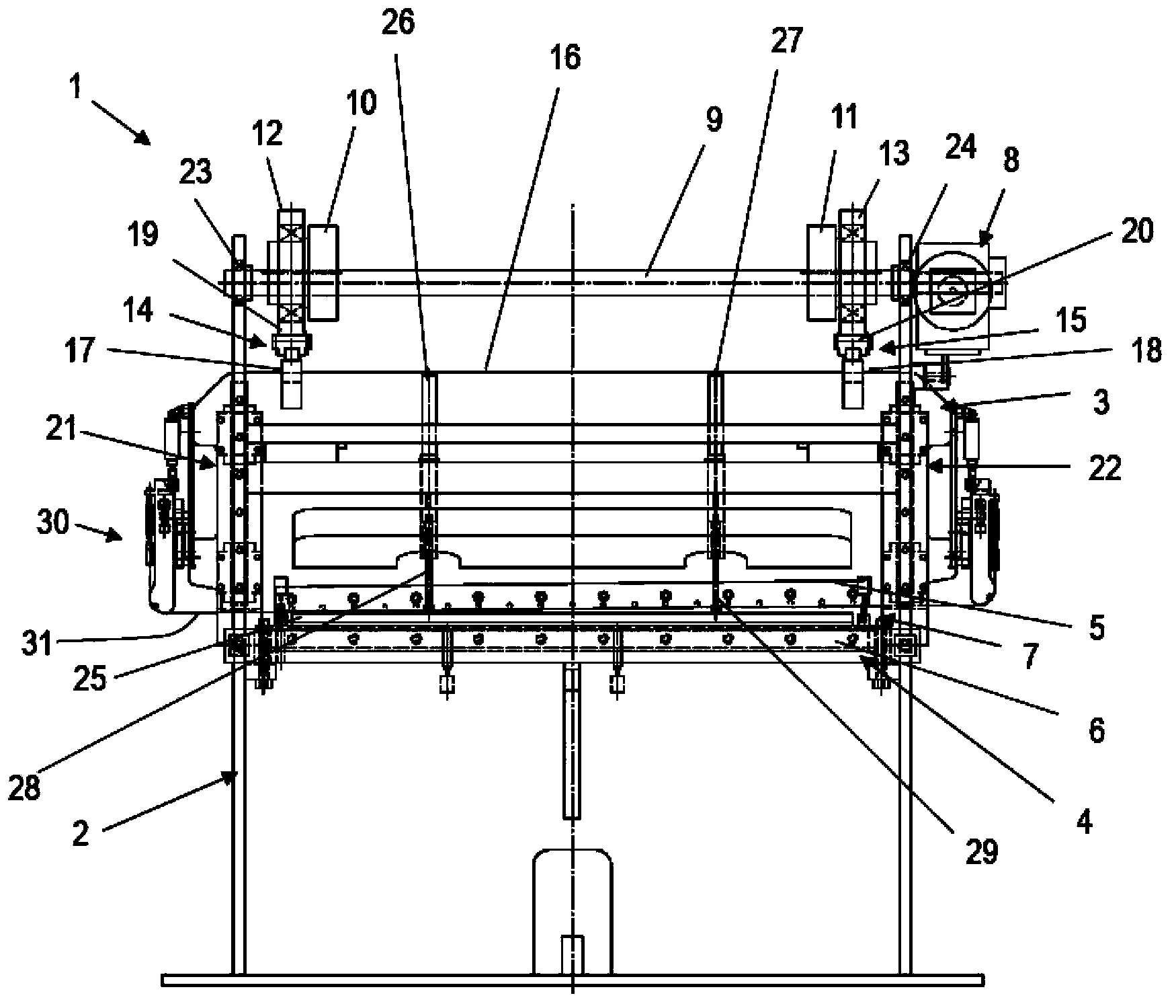
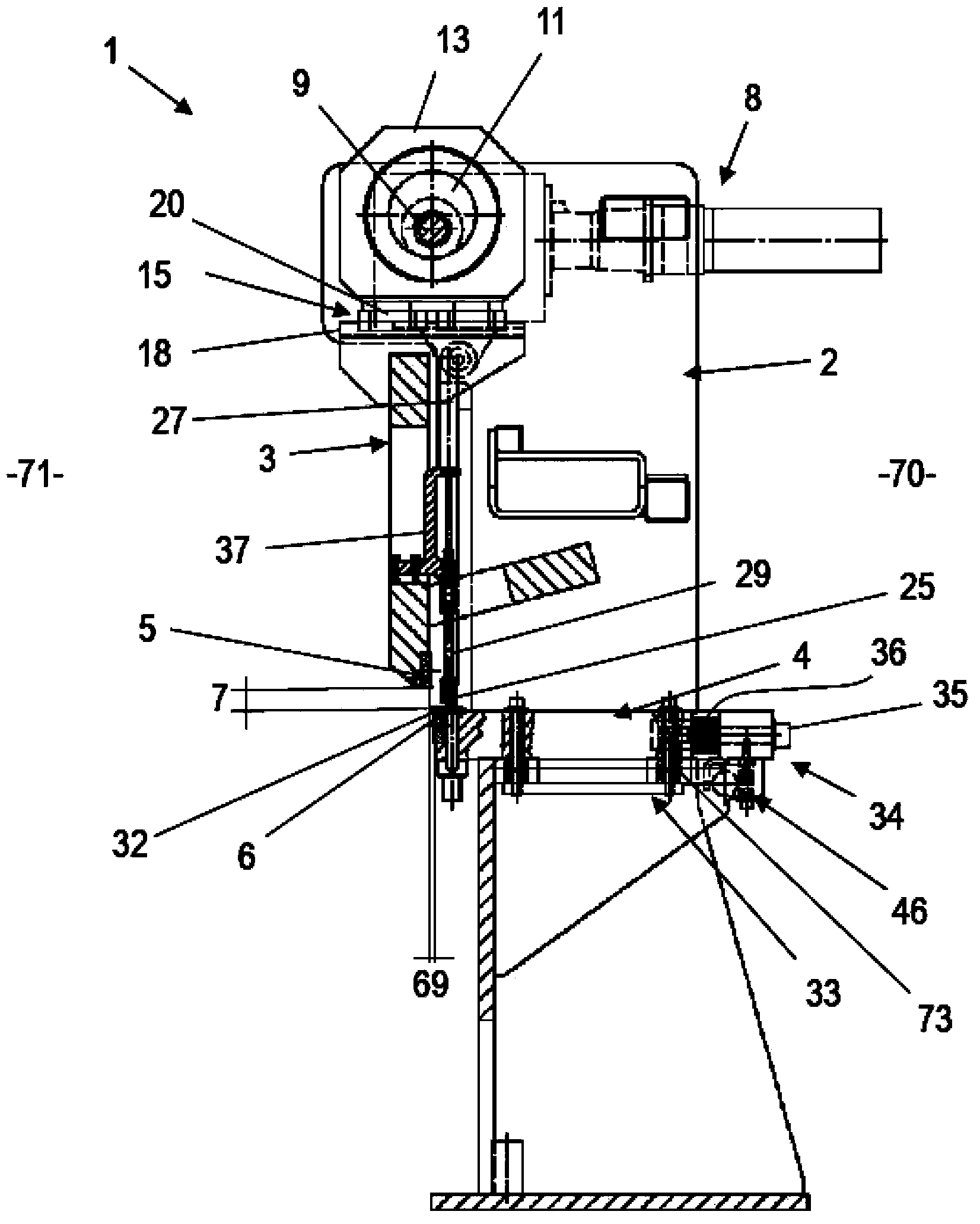
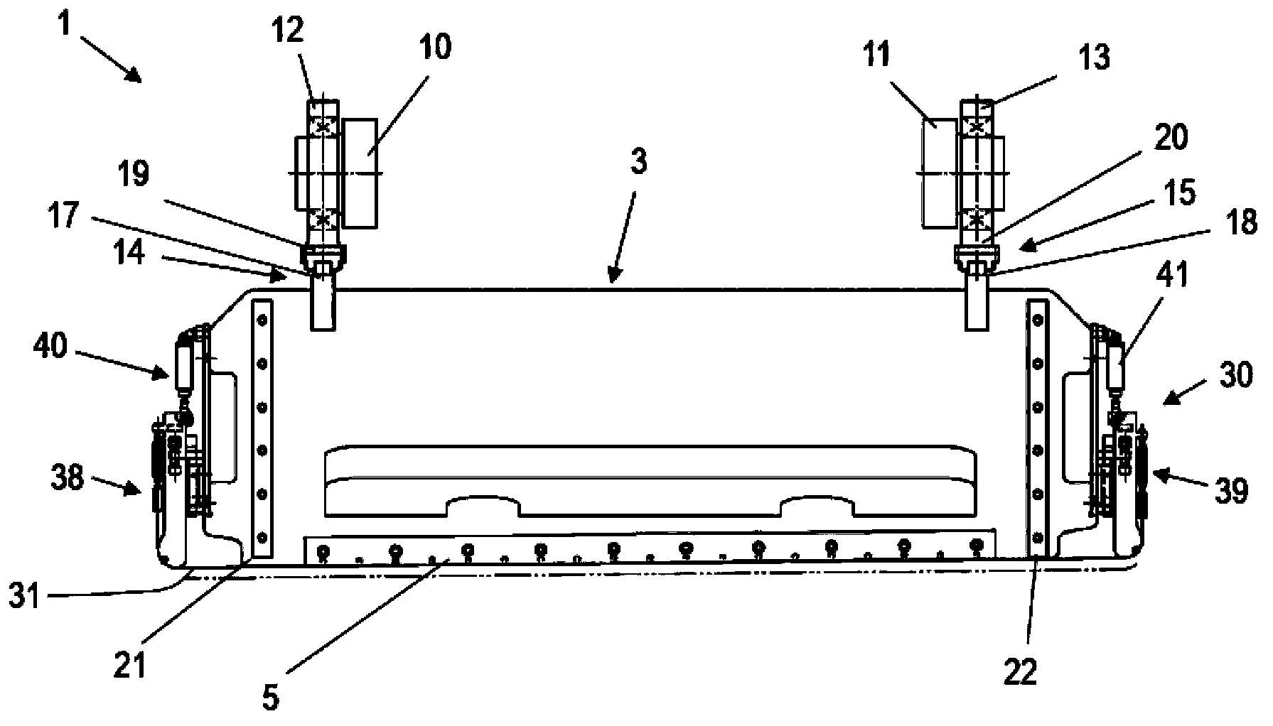
[0036] figure 1 A cutting machine 1 for cutting thin adhesive tapes is shown, having a knife holder 3 guided on a main frame 2 and a table 4 arranged immovably in vertical direction relative to the main frame 2 . In the lower region of the tool holder, an upper blade 5 is fastened, which interacts with a lower blade 6 which is arranged on the table 4 . Between the upper blade 5 and the lower blade 6 a cutting edge 7 is formed in the vertical direction and a cutting gap 69 is arranged in the horizontal direction.

[0037] for cutting according to figure 1 In the view of the belt introduced into the plane of view by the platen 4, the knife holder 3 with the upper blade 5 moves vertically downwards, so that the knife edge 7 closes and the belt is drawn between the upper blade 5 and the lower blade 6 cutting. In order to move the tool holder 3 , a drive 8 is provided which is fastened to the main frame 2 . The drive 8 drives a drive shaft 9 , which is mounted eccentrically in ...


PUM


Abstract

The invention relates to a cutting machine for cutting sticky ribbons, particularly the ribbon comprises sticky thin cord fabric material comprising spinning silk and / or steel wire. The cutting machine comprises a main frame (2), a knife rest (3), a platen (4) with a lower blade (6), and a driving device (8) with a driving shaft (9), wherein the knife rest (3) with an upper blade (5) can vertically move and support on the main frame (2), a knife edge (7) is arranged between the upper blade (5) and the lower blade (6), the driving device (8) is used for driving the knife rest (3) with the upper blade (5) to vertically move relative to the main frame (2). In order to realize high hardness, the driving shaft (9) eccentrically supports in at least one bearing shell (12 or 13), and the bearing shell only can horizontally move and support on the knife rest (3) through linear guide parts (14 and 15).

Description

technical field [0001] The invention relates to a cutting machine for cutting adhesive thin strips. Such belts are in particular belts made of a viscous and thin ply material with textile and / or steel wires. The cutting machine comprises a main frame, a tool rest with an upper blade vertically movably supported on the main frame, a platen with a lower blade, and a driving device with a drive shaft for producing strips. Vertical movement of the tool holder with the upper blade relative to the main frame. The strip can be passed through a knife edge configured between the upper and lower blades to cut strips of the desired width. To carry out the cutting, the upper blade passes the lower blade vertically and the knife edge is closed thereby. Background technique [0002] The orientation parameter "vertical" or "horizontal" relates to the operational readiness of the cutting machine, in which no mathematically strict orientation is required, but small deviations from the ver...

Claims


Application Information

Patent Timeline
Patent Type & Authority Applications(China)
IPC IPC(8): B29D30/46B26D5/08B26D7/02B26D7/18B26D7/26B26D7/06
Inventor 拉尔夫·克伦纳瓦尔特·弗利格
Owner KARL EUGEN FISCHER GMBH
Why Eureka
Try Eureka