Well bottom gas-liquid separator

A gas-liquid separator and gas-liquid separation technology, which is applied in wellbore/well components, production fluid, earthwork drilling and production, etc., can solve the problems that condensate gas reservoirs cannot be fully applied, only consider practicality, and reduce gas well productivity, etc. , to achieve strong practical value, avoid waste and save space

Inactive Publication Date: 2014-12-17
SOUTHWEST PETROLEUM UNIV
View PDF8 Cites 9 Cited by
  • Summary
  • Abstract
  • Description
  • Claims
  • Application Information

AI Technical Summary

Problems solved by technology

[0002] Condensate gas reservoirs are a special kind of gas reservoirs. There is an anti-condensation zone. When the temperature and pressure drop, the gas condenses into condensate oil. Therefore, many problems are often encountered in the development process: due to the change of formation temperature and pressure, Condensate gas condenses into condensate oil, which will cause formation blockage, reduce gas well productivity or even stop production; condensate gas condenses into condensate oil due to temperature and pressure changes in the wellbore, and condensate oil adheres to the wellbore, increasing friction, Reduce production capacity. When the liquid-carrying capacity of the gas well is insufficient, the condensate oil will fall back to the bottom of the well, which will also cause formation blockage, reduce the

Method used


Image

  • Well bottom gas-liquid separator
  • Well bottom gas-liquid separator

Examples


Embodiment Construction

[0033] The solution of the present invention will be further described in detail below in conjunction with the accompanying drawings and specific embodiments,

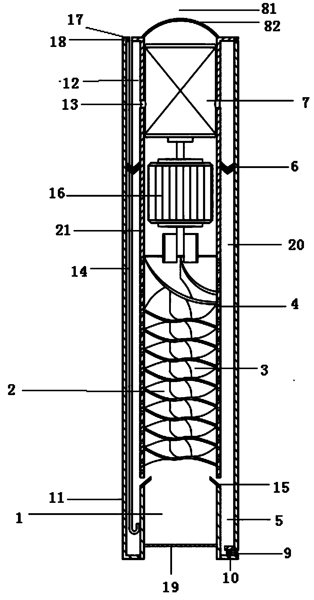
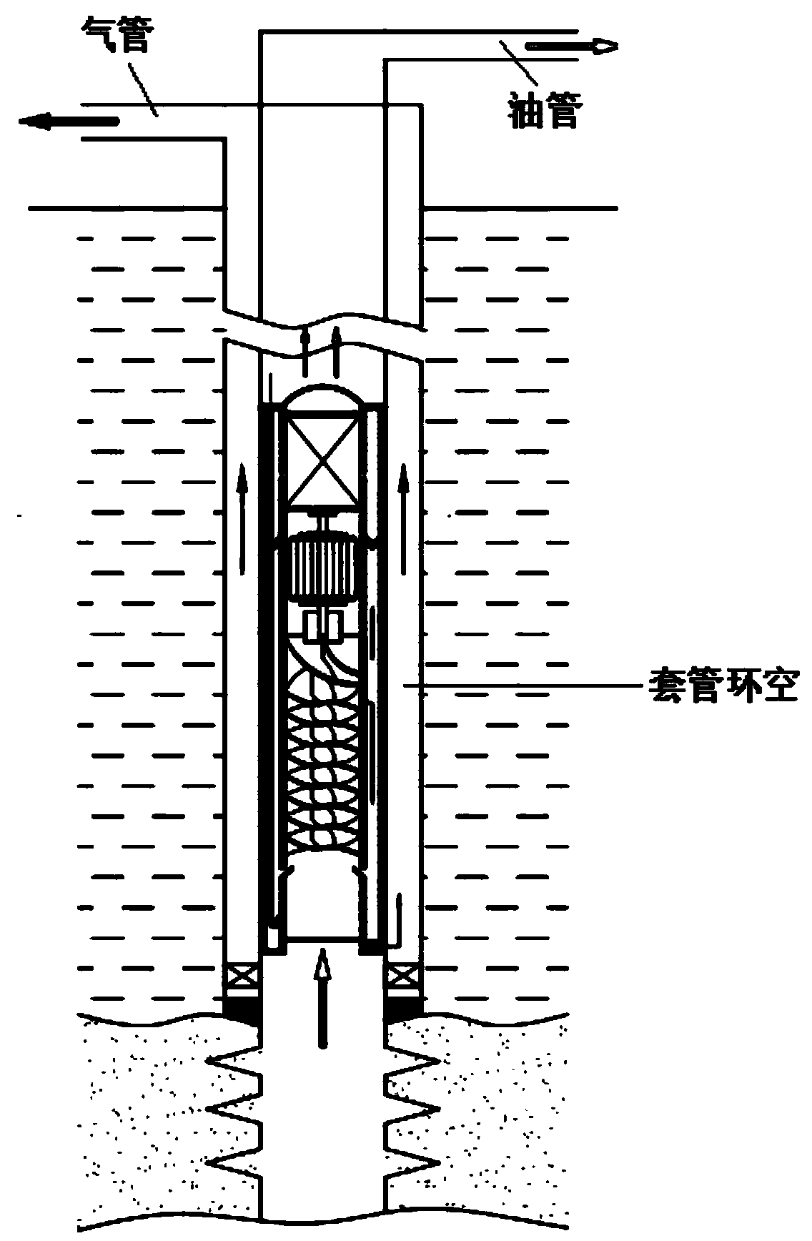
[0034] Such as figure 1 , 2 Shown: a bottom hole gas-liquid separator, the gas-liquid separator includes:

[0035] The cylindrical part 21 is surrounded by a cylinder wall defining the air inlet 1 and the air outlet 81, and the air inlet 1 and the air outlet 81 have a certain axial distance;

[0036] The gas-liquid separation chamber 2, the through-axis motor 16, and the compressor 7 are sequentially arranged on the same axis in the cylindrical part 21 between the air inlet and the air outlet;

[0037] The liquid collecting convex plate 82 with protruding holes is sealed on the air outlet 81 at the top of the cylindrical part 21;

[0038] The cavity between the cylindrical part 21 and the outer sleeve 11 forms a gravity separation part 20, the top of the gravity separation part 20 is sealed, and the wall of the cyli...


PUM


Abstract

The invention provides a well bottom gas-liquid separator, which comprises a tubular part (21), a gas-liquid separation chamber (2), a through shaft motor (16) and a compressor (7), wherein a tube wall defining an air inlet (1) and an air outlet (81) is arranged around the tubular part (21), the air inlet (1) and the air outlet (81) have a certain axial distance, the gas-liquid separation chamber (2), the through shaft motor (16) and the compressor (7) are sequentially arranged in the tubular part (21) arranged between the air inlet and the air outlet on the same axial line, a liquid collecting convex plate (82) provided with a projected hole seals and covers the air outlet (81) formed in the top of the tubular part (21), a cavity formed between the tubular part (21) and an outer sleeve (11) forms a gravity separation part (20), the top of the gravity separation part (20) is sealed, an air inlet hole (13) is formed in a wall of the tubular part (21) corresponding to the compressor (7), a plurality of exhaust/liquid discharge holes (4) are formed in the tubular part (21) provided with the gas-liquid separation chamber (2) arranged in the middle part of the gravity separation part (20), a liquid collecting groove (5) is formed by a liquid blocking plate (15) and the outer sleeve (11) at the end, near the air inlet (1), of the gravity separation part (20), and a condensed liquid recovery pool (12) is positioned on the top of the gravity separation part (20).

Description

technical field [0001] The invention relates to the field of development of condensate gas reservoirs, conventional gas reservoirs and coal bed gas reservoirs, in particular to a gas-liquid separator at the bottom of a well. Background technique [0002] Condensate gas reservoirs are a special kind of gas reservoirs. There is an anti-condensation zone. When the temperature and pressure drop, the gas condenses into condensate oil. Therefore, many problems are often encountered in the development process: due to the change of formation temperature and pressure, Condensate gas condenses into condensate oil, which will cause formation blockage, reduce gas well productivity or even stop production; condensate gas condenses into condensate oil due to temperature and pressure changes in the wellbore, and condensate oil adheres to the wellbore, increasing friction, Reduce production capacity. When the liquid-carrying capacity of the gas well is insufficient, the condensate oil will ...

Claims


Application Information

Patent Timeline
IPC IPC(8): E21B43/38
Inventor 彭小龙王超文王铭伟王可可李扬杨帆莫非朱苏阳张岌强
Owner SOUTHWEST PETROLEUM UNIV
Why Eureka
Try Eureka