
A rotary buffer valve

A technology of rotary buffer and valve body, which is used in fluid pressure actuating devices, servo motor components, mechanical equipment, etc., can solve the problems of increased manufacturing and design costs, cumbersome inventory management, and no rotation of the mechanism, and achieves a compact structure. Wide application, smooth stop effect

Active Publication Date: 2016-11-30
XCMG HYDRAULICS CO LTD
View PDF4 Cites 0 Cited by
  • Summary
  • Abstract
  • Description
  • Claims
  • Application Information

AI Technical Summary

Problems solved by technology

This technology has the following deficiencies: 1. The rotary buffer valve mentioned in the patent is connected to port A and port B of the rotary motor through a relief valve and a one-way valve to realize the buffering function
Due to the wide variety of truck cranes, the cost of manufacturing and design has increased significantly, and inventory management has become more cumbersome; 3. The spool of the solenoid valve is a slide valve-type sealing structure, which has a large amount of leakage, and it is easy to cause the mechanism to fail to rotate; 4. Adopt Transition plate structure, easy to leak oil at the joint surface of the transition plate

Method used


Image

  • A rotary buffer valve

Examples


Embodiment Construction

[0019] The following is a specific embodiment of the present invention, and the present invention will be further described in conjunction with the accompanying drawings.

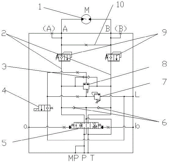
[0020] Such as figure 1 As shown, a rotary buffer valve has two main oil passages 2 in the valve body, and the valve body is also opened with pilot control oil port a, pilot control oil port b, oil inlet P, oil return port T, drain Oil port L and oil port A and oil port B connected to the oil inlet and outlet of the rotary motor; three-position six-way hydraulic control reversing valve 5, main overflow valve 8 and free-slip solenoid valve 4 are mainly installed in the valve body; three-position six-way The valve stem of the hydraulic control reversing valve 5 is provided with an oil return orifice to improve system stability. The left position of the three-position six-way hydraulic control reversing valve 5 is connected to the left and right channels, and the middle channel is disconnected. The left and r...


PUM


Abstract

The invention discloses a rotary buffer valve used in a hydraulic system of a crane. It includes a valve body with two main oil passages. The valve body also has a pilot control oil port a, a pilot control oil port b, an oil inlet P, an oil return port T, an oil drain port L and a rotary motor connected to the oil inlet and outlet. The oil port A and oil port B of the port; the valve body is mainly equipped with a three-position six-way hydraulic control reversing valve, a main relief valve and a free-slip solenoid valve; two main oil passages leading to A and B oil ports Each is equipped with an adjustable back pressure valve; there is a throttling oil passage connecting the two main oil passages between the two main oil passages, and the intersection point of the throttling oil passage and the main oil passage is more Closer to port A and port B. The invention has the advantages of compact structure, small volume, low cost, convenient installation and operation, strong adaptability, wide application, good fretting performance, precise rotary positioning and stable stop.

Description

technical field [0001] The invention relates to the technical field of hydraulic systems of automobile cranes, in particular to a rotary buffer valve used in hydraulic systems of cranes. Background technique [0002] The traditional car crane slewing mechanism generally has the following characteristics according to the actual use requirements, that is, it can start quickly and stop quickly; the impact of start and stop is small and stable; it must be able to keep the lead weight of the steel cable and the arm frame to rotate accurately and synchronously, etc. , so that the crane can lift the goods safely, quickly and conveniently. The slewing buffer valve used by cranes now integrates various functions required for the slewing working conditions of the crane to realize functions such as slewing steering, overload buffer protection, and free sliding. The impact is large when it stops, and one product cannot be applied to various main engines. Different types of main valve s...

Claims


Application Information

Patent Timeline
Patent Type & Authority Patents(China)
IPC IPC(8): F15B13/02
Inventor 刘帮才戚振红张凯张洪波
Owner XCMG HYDRAULICS CO LTD
Learn More