

An unobstructed tracking method for a dual-axis solar photovoltaic power generation system
A solar photovoltaic and power generation system technology, applied in the field of solar panel tracking, can solve the problems of lower power generation efficiency, front solar panels blocking rear solar panels, and increased land area occupied by the power generation system.
- Summary
- Abstract
- Description
- Claims
- Application Information
AI Technical Summary
Problems solved by technology
Method used
Image

Examples
Embodiment 1
[0094] In the implementation example 1, the specific measurement time is eight o'clock Beijing time.
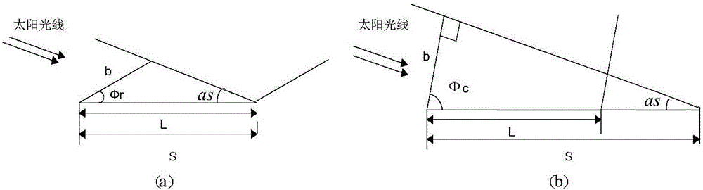
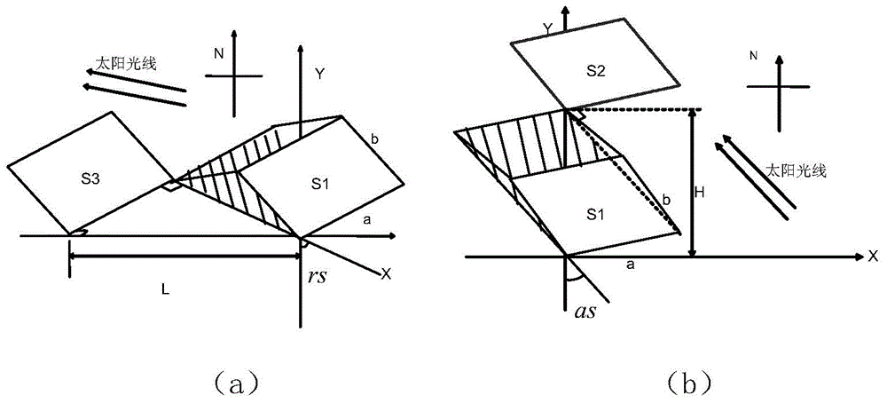
[0095] 1. Through formula (1)(2)(3)(4)(5), the solar elevation angle as=11.33° and the solar azimuth angle rs=-73.12° are obtained. Then there are |cos rs|=0.29, |sin rs|=0.96.
[0097] 3. L'=L|sin rs|=8.61, S=b / sin as=10.18. Therefore S > L', so the shadow of S1 does occlude S3.
[0098] 4. According to formula (11), adjust the inclination angle of the solar panel Make the shadow of S1 just not block S3.
[0099] By realizing the above steps, the method for tracking the sun without occlusion at this time is completed.
Embodiment 2
[0101] In the implementation example 2, the specific measurement time is ten o'clock Beijing time.
[0102] 1. Through formula (1)(2)(3)(4)(5), the sun elevation angle as=33.26° and the sun azimuth angle rs=-51.17° are obtained. Then there are |cos rs|=0.54, |sin rs|=0.78.
[0103] 2. |cos rs|≥a / L=0.33, |sin rs|≥a / H=0.6. So the shadow of S1 may occlude S4.
[0104] 3. S=b / sinas=3.65. Therefore S
[0105] 4. At this time, it belongs to the situation of no occlusion, according to formula (10), adjust the inclination angle of the solar panel
[0106] By realizing the above steps, the method for tracking the sun without occlusion at this time is completed.
[0107] At present, the tracking method of keeping the surface of the solar panel perpendicular to the sun's rays is widely used, and the existing power generation is calculated as follows:
[0108] Q r =abAXYsin(as+φ r ) (15)
[0109] Q=abAXY (16)
[0110] Q c=LAX(Y-1)b...
PUM
 Abstract
Description
Claims
Application Information