Location method and device for compressor rotor of refrigerator with inverter
A technology of compressor rotor and positioning method, applied in the direction of electronic commutator, etc., can solve the problems of high starting current, shortening compressor life, compressor starting failure, etc., to achieve stable performance of reducing noise, prolong compressor life, avoid Startup failure effect
- Summary
- Abstract
- Description
- Claims
- Application Information
AI Technical Summary
Problems solved by technology
Method used
Image
Examples
Embodiment 1
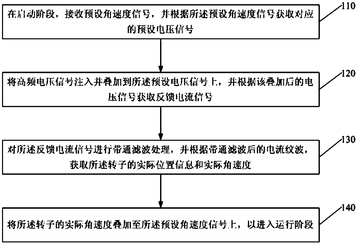
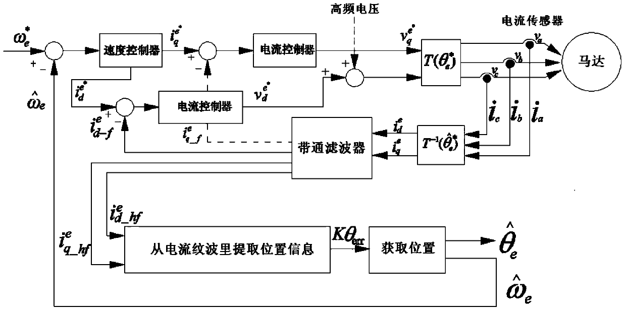
[0077] refer to figure 1 , is a flow chart of a method for positioning the compressor rotor of an inverter refrigerator provided in Embodiment 1 of the present invention. The technical solution of this embodiment can be applied to quickly detect the position of the compressor rotor and precisely locate it during the start-up phase of the compressor of the equipment. The situation of the compressor, as well as the real-time detection of the position of the compressor rotor and the precise positioning of the compressor during the operation phase. The device may be any electronic device with a compressor, typically such as an inverter refrigerator. The refrigerator's compressor is divided into three different phases, the start-up phase, the low speed operation phase and the steady operation phase. The positioning method of the compressor rotor can detect and accurately locate the compressor rotor in different stages of the compressor in real time and quickly. The method may be ...
Embodiment 2
[0180] refer to Figure 4 , is a structural diagram of a positioning device for a compressor rotor of an inverter refrigerator provided in Embodiment 2 of the present invention. The positioning device includes: a voltage acquisition module 210 , a high frequency superposition module 220 , a bandpass filter module 230 , and an angular velocity superposition module 240 .
[0181] Among them, the obtaining voltage module 210 is used to receive the preset angular velocity signal, and obtain the corresponding preset voltage signal according to the preset angular velocity signal; the high frequency superimposing module 220 is used to inject and superimpose the high frequency voltage signal into the On the preset voltage signal, and obtain the feedback current signal according to the superimposed voltage signal; the band-pass filter module 230 is used to perform band-pass filter processing on the feedback current signal, and according to the current ripple after the band-pass filter,...
PUM
 Abstract
Description
Claims
Application Information
 - R&D
- Intellectual Property
- Life Sciences
- Materials
- Tech Scout
- Unparalleled Data Quality
- Higher Quality Content
- 60% Fewer Hallucinations
Browse by: Latest US Patents, China's latest patents, Technical Efficacy Thesaurus, Application Domain, Technology Topic, Popular Technical Reports.
© 2025 PatSnap. All rights reserved.Legal|Privacy policy|Modern Slavery Act Transparency Statement|Sitemap|About US| Contact US: help@patsnap.com


