Three-phase magnetic cores for magnetic induction devices and methods for manufacturing them

A magnetic induction device and magnetic core technology, which is applied in the fields of magnetic core manufacturing, transformer/inductor magnetic core, inductor/transformer/magnet manufacturing, etc., can solve complex production technology problems, reduce electrical loss, simplify assembly and disassembly, Effect of reduced diameter and weight

Inactive Publication Date: 2014-12-17
U T T UNIQUE TRANSFORMER TECH
View PDF14 Cites 9 Cited by
  • Summary
  • Abstract
  • Description
  • Claims
  • Application Information

AI Technical Summary

Problems solved by technology

However, the interleaved ring structure proposed in this patent requires very

Method used


Image

  • Three-phase magnetic cores for magnetic induction devices and methods for manufacturing them
  • Three-phase magnetic cores for magnetic induction devices and methods for manufacturing them
  • Three-phase magnetic cores for magnetic induction devices and methods for manufacturing them

Examples


Embodiment Construction

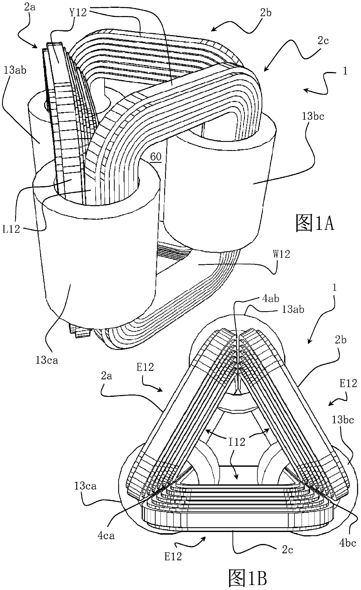
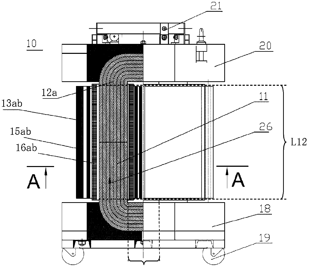
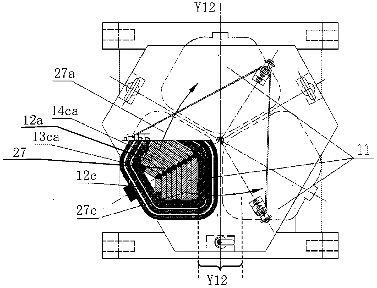
[0062] This application is generally directed to magnetic core circuits for three-phase magnetic induction devices, such as, but not limited to, three-phase choke coils and three-phase transformers. The three-phase magnetic core circuit of the present invention is constructed of a magnetic core frame having a stepped configuration formed on at least one face of the frame and extending along their sides. The core loop is constructed by placing frames locally adjacent one another to form a triangular (triangular prism) structure, wherein the stepped sides of each frame evenly engage the adjacent positioned frames. Stepped sides. The evenly joined sides of these frames form the magnetic core legs on which the coil modules of the magnetic induction device are to be placed.

[0063] As should be apparent from the following disclosure, this core design improves the distribution of magnetic flux in the core circuit and reduces electromagnetic losses that typically occur in the core....


PUM

PropertyMeasurementUnit
Slopeaaaaaaaaaa

Abstract

Three-phase magnetic cores for magnetic induction devices (e.g., transformers, coils, chokes), and methods for manufacturing them, are disclosed. The magnetic cores are generally constructed from three generally rectangular magnetic core frames having a stair-stepped configuration extending along side portions of the frames. The frames are arranged to form a triangular prism structure such that side portions of locally adjacent frames are uniformly engaged to form three core legs over which coils of a three-phase magnetic induction device may be placed.

Description

technical field [0001] The present invention relates to three-phase magnetic induction devices, magnetic circuit cores used in such devices, and methods for their manufacture. Background technique [0002] Magnetic induction devices (eg, power transformers, choke coils, etc.) are designed to transfer electrical energy between inductively coupled wound conductors (coils) based on mutual inductance effects. For example, in a power transformer, an alternating current supplied to a primary winding that is inductively coupled to the transformer core creates a magnetic flux in the core that induces an electromotive force (EMF) or Voltage. [0003] A three-phase transformer typically includes a magnetic core circuit and three coil modules inductively coupled to the magnetic core circuit. Each coil module is usually constructed from a primary winding and a secondary winding. State-of-the-art three-phase power transformers typically utilize a so-called "E+1" core construction (in ...

Claims


Application Information

Patent Timeline
IPC IPC(8): H01F27/25H01F30/12H01F41/02
CPCH01F27/25H01F30/12H01F41/0213H01F1/15333Y10T29/49071Y10T29/49075H01F3/04H01F41/022
Inventor 埃列塞尔·阿达尔Y·波罗京斯基
Owner U T T UNIQUE TRANSFORMER TECH
Why Eureka
Try Eureka