
A Viscous Medium External Pressure Forming Method for Large Curvature Thin-walled Components

A technology of thin-walled components and viscous media, which is applied in the field of forming large-curvature thin-walled components. It can solve the problems of easy instability and wrinkling of formed parts, thinning of the wall thickness of formed parts, and poor forming accuracy, so as to avoid wall thickness reduction. and wrinkling, large diameter reduction, and strong strain rate sensitivity

Active Publication Date: 2016-06-22
HARBIN INST OF TECH
View PDF4 Cites 0 Cited by
  • Summary
  • Abstract
  • Description
  • Claims
  • Application Information

AI Technical Summary

Problems solved by technology

[0003] The present invention solves the simple external pressure forming of large-curvature thin-walled components. When the two ends of the blank are constrained, the wall thickness of the formed part is severely reduced or even broken; , also in order to solve the problems of complex mold, frequent forming, poor forming precision and high cost in multi-pass forming, a viscous medium external pressure forming method for large curvature thin-walled components is provided

Method used


Image

  • A Viscous Medium External Pressure Forming Method for Large Curvature Thin-walled Components
  • A Viscous Medium External Pressure Forming Method for Large Curvature Thin-walled Components
  • A Viscous Medium External Pressure Forming Method for Large Curvature Thin-walled Components

Examples


specific Embodiment approach 1

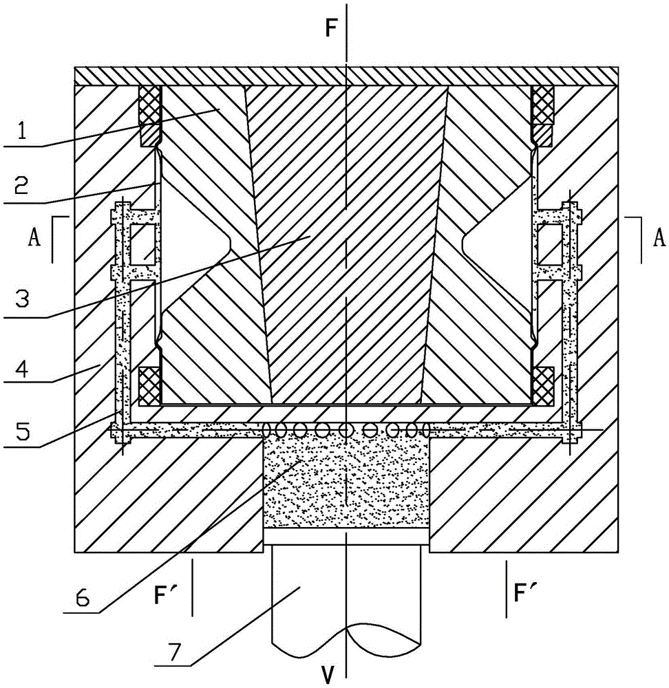
[0027] Specific implementation mode one: combine Figure 1 to Figure 8 Describe this implementation mode, this implementation mode is realized through the following steps:

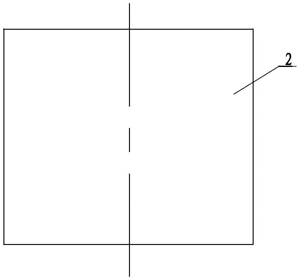
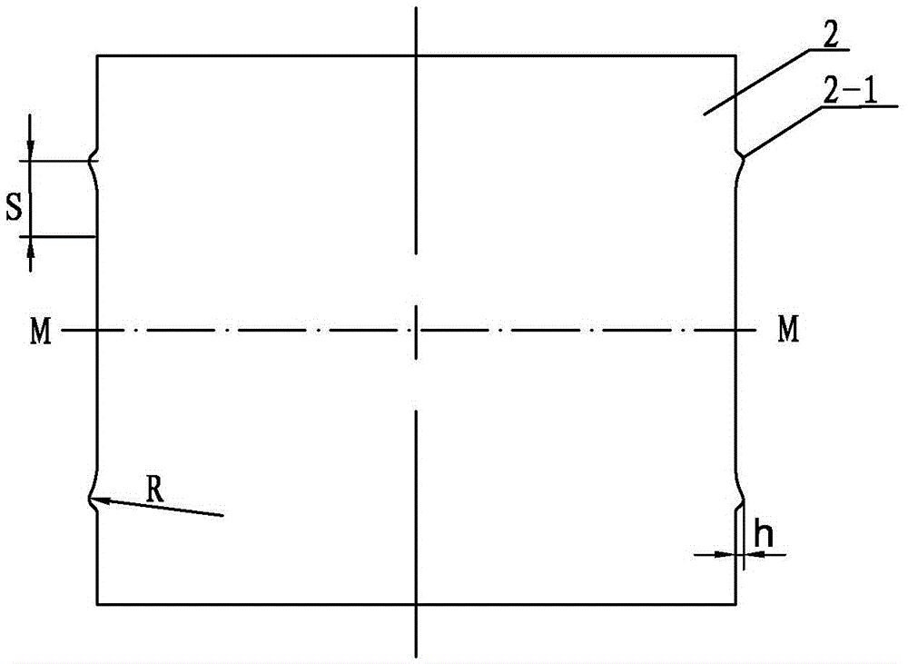
[0028] Step 1, making the tube blank 2: roll and weld the plate to form a cylinder, see figure 1 , the material flow control rib 2-1 is arranged symmetrically on the cylinder wall with the cylinder length center M-M as the reference, the distance s between the material flow control rib 2-1 and the entrance of the variable diameter area is 5 mm to 30 mm, see figure 2 ; The structural shapes of the material flow control ribs 2-1 at both ends of the billet 2 can be different. Through the resistance of the material flow control rib 2-1, the inflow of the material at the end is adjusted and controlled, so that the wall thickness of the formed part is less thinned and wrinkle-free.

[0029] Step 2, the tube blank 2 is loaded into the external pressure forming mold: the tube blank 2 is loaded into the core mo...

specific Embodiment approach 2

[0033] Specific implementation mode two: combination figure 2 To describe this embodiment, the distance s between the material flow control rib 2 - 1 and the entrance of the variable diameter area in Step 1 of this embodiment is 20 mm. For general large-curvature external pressure parts, the forming quality is better, and for special formed parts, it is necessary to reasonably adjust and control the distance s between the ribs and the entrance of the mandrel. Other steps are the same as in the first embodiment.

specific Embodiment approach 3

[0034] Specific implementation mode three: combination Figure 1 to Figure 8 To illustrate this embodiment, the material of the tube blank 2 in step 1, step 2 and step 3 of this embodiment is stainless steel or superalloy. For external pressure forming of large curvature parts, if control ribs are not used, the diameter reduction is small, and it is difficult to form large curvature parts. However, if the control ribs are used for forming, the diameter reduction is large, and larger curvature parts can be formed. Other steps are the same as those in Embodiment 1 or 2.


PUM

PropertyMeasurementUnit
thicknessaaaaaaaaaa
viscosityaaaaaaaaaa

Abstract

A viscous medium external pressure forming method for large-curvature thin-walled components, which relates to a large-curvature thin-walled component forming method to solve the simple external pressure forming of large-curvature thin-walled components. When there are constraints at both ends of the blank, the wall thickness of the formed part Severe thinning or even rupture; when the two ends of the blank are not restrained, the formed part is prone to instability and wrinkling. Method: 1. The plate is rolled and welded to form a cylinder, and the material flow control ribs are arranged symmetrically on the wall of the cylinder with the length center of the cylinder as the reference; 2. The cylinder blank is put into the external pressure forming mold; 3. Push the plunger so that the viscous soft mold material is injected and loaded from the outside of the part through the injection channel, and the tube billet partially shrinks and deforms until it fits the mandrel; 4. Open the mold, take out the externally formed part and remove the viscous soft mold material to obtain Forming components; 5. Remove the material flow control ribs at both ends to obtain finished products. The invention is used for forming large-curvature thin-walled parts.

Description

technical field [0001] The invention relates to a method for forming a thin-walled component with large curvature, in particular to a method for forming a thin-walled component with large curvature by external pressure with a viscous medium. Background technique [0002] A thin-walled member with large curvature is a typical shell structure, such as Figure 9 shown. At present, the methods commonly used to process such parts are: 1. Perform simple soft mold compression molding on the deformation zone: when there are no constraints at both ends of the blank, the forming principle is as follows: Figure 10 As shown, since the two ends of the billet are in a free state, the material of the tube blank flows to the deformation zone under the action of the adhesive stress of the viscous soft mold material. Defects such as instability and wrinkling seriously reduce the surface quality of the formed part; when there are constraints 8 at both ends of the blank, the forming principle...

Claims


Application Information

Patent Timeline
Patent Type & Authority Patents(China)
IPC IPC(8): B21D26/033
Inventor 王忠金相楠易军程超
Owner HARBIN INST OF TECH
Learn More