
Non-uniform-thickness rubber spherical hinge diameter reducing device and method

A rubber ball joint, non-uniform thickness technology, applied in the diameter reduction field of thick rubber ball joints, can solve the problems of high tooling cost, limited diameter reduction at one time, diameter deviation, etc., to improve reliability and accuracy, improve shrinkage Diameter reliability, reducing the effect of diameter reduction difference

Active Publication Date: 2020-09-22
ZHUZHOU TIMES NEW MATERIALS TECH
View PDF23 Cites 0 Cited by
  • Summary
  • Abstract
  • Description
  • Claims
  • Application Information

AI Technical Summary

Problems solved by technology

[0004] (1) For example, "Application Research of Radial Reduction Process in Ball Joint of Oil Pressure Shock Absorber" (MN61-1141 / TQ), "Development and Development of Ball Joint Reduction Machine" (11-1812 / TQ); "An Automobile Swing Arm Bushing Reducing Tooling" (MN201822049808.5), "Leaf Spring Back Bushing The problem of the tight reduction is that the working part of the reduction mold is a circular inner hole. For the structural ball joint discussed in the present invention, due to the spherical joint, the rubber layer has a partially hollowed out structure, and after the diameter is reduced, the hollow direction and The actual size deviation is very large, resulting in unqualified cylindricity of the outer surface of the product
[0005] (2) The radial precompression method described in "A Combined Radial Precompression Die for Rubber Bushing" (MN201420571594.7) belongs to the axial extrusion type diameter reduction of workpiece movement. The problem is that the lower mold is divided into The upper block and the lower block have a two-layer structure. The working area is distributed on the upper block. The length of the working area is relatively short. After extrusion, there will be a large diameter deviation at different positions in the height direction of the product. The assembly area and the working area are both circular holes, and the transition The area is a tapered hole. When the diameter reduction exceeds 2mm, the taper hole in the transition area has a large step, and the product jacket will be scratched after extrusion. At the same time, the structure in the patent cannot realize automatic operation, and the production efficiency is low.
[0006] (3) The radial pre-compression method described in "Rubber Bushing Squeeze Die" (MN201010133169.6) belongs to the axial extrusion type diameter reduction of workpiece movement. Products with large diameter reduction need to be divided into multiple times, the operation is cumbersome, and the cost of tooling is high
[0007] It is the research and development purpose of the present invention to solve the technical problem that there is a large deviation between the space and the real dimension after the diameter is reduced, which leads to the unqualified cylindricity of the product's outer circle

Method used


Image

  • Non-uniform-thickness rubber spherical hinge diameter reducing device and method
  • Non-uniform-thickness rubber spherical hinge diameter reducing device and method
  • Non-uniform-thickness rubber spherical hinge diameter reducing device and method

Examples


Embodiment Construction

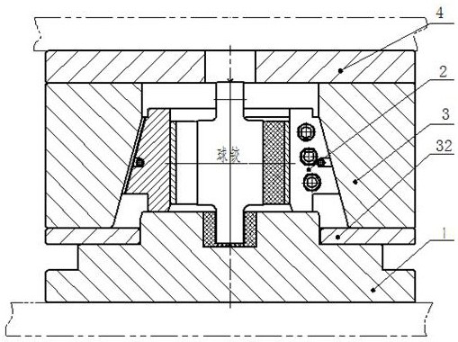
[0037] Combine below Figure 3 to Figure 8 Embodiments of the present invention are described in detail.

[0038] Non-equal-thickness rubber ball joint diameter reducing device, including a base 1 supporting the ball joint vertically, a chuck valve mold assembly 2 placed on the base and capable of surrounding the ball joint in a circumferential direction, and used for aligning the chuck valve mold assembly 2 The middle mold 3 that applies radial pressure and the upper module 4 used to drive the middle mold 3 up and down, the middle mold 3 is set on the chuck valve mold assembly 2 and cooperates with the cone surface of the chuck valve mold assembly 2, the chuck The valve mold assembly 2 radially compresses the spherical hinge as the middle mold 3 descends, and the chuck valve mold assembly 2 is formed by sequentially splicing a plurality of valve molds along the circumferential direction, and is characterized in that the valve molds are divided into pairs of spherical The hol...


PUM


Abstract

The invention provides a non-uniform-thickness rubber spherical hinge diameter reducing device and method. The non-uniform-thickness rubber spherical hinge diameter reducing device comprises a base supporting a spherical hinge in the vertical direction, a chuck petal die assembly which is arranged on the base and capable of circumferentially surrounding the spherical hinge, a middle die used for exerting radial pressure on the chuck petal die assembly and an upper die block used for driving the middle die to ascend and descend. The middle die is installed on the chuck pedal die assembly in a sleeving manner and is in conical surface fit with the chuck petal die assembly. The chuck petal die assembly compresses the spherical hinge in the radial direction along with descent of the middle die. The chuck petal die assembly is formed by sequentially splicing multiple pedal dies in the circumferential direction. The petal dies are divided into hollow direction petal dies conducting radial compression in the hollow direction of the spherical hinge and solid direction petal dies conducting radial compression in the solid direction of the spherical hinge. The radial compression amount exerted by the hollow direction petal dies on the spherical hinge rubber layer is smaller than the radial compression amount exerted by the solid petal dies on the spherical direction hinge rubber layer. The non-uniform-thickness rubber spherical hinge diameter reducing device and method can compensate for the dimension deviation caused by rubber rebound difference between the hollow direction and thesolid direction after diameter reduction, reduce the diameter reduction amount difference between the hollow direction and the solid direction of the spherical hinge, improve the cylindricity of the spherical hinge after diameter reduction and improve the diameter reduction reliability and accuracy, and the practicability of the diameter reducing device is higher.

Description

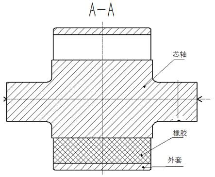
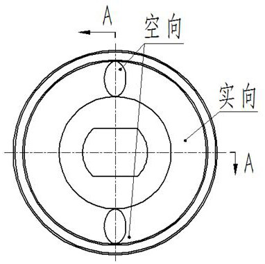
technical field [0001] The invention relates to a non-uniform-thickness rubber ball joint diameter reduction device and method, which are used for the diameter reduction of non-uniform-thickness rubber ball joints. Background technique [0002] The non-equal thickness rubber spherical joint structure with hollow solid structure is shown in the attached Figure 1~2 As shown, it is composed of a metal jacket, a metal mandrel, and rubber. The rubber layer between the jacket and the mandrel is designed with an opening structure, and the openings are symmetrically distributed at 180°. The one with openings is called empty, and the one without openings is called empty. The opening side is called the solid direction. After vulcanization and molding, the rubber cools and shrinks, the rubber is firmly bonded to the jacket and the mandrel, and there is no space for the rubber to shrink, resulting in tensile stress between the molecules. During the working process of the ball joint, i...

Claims


Application Information

Patent Timeline
Patent Type & Authority Applications(China)
IPC IPC(8): B29C67/00B29C33/30
CPCB29C33/302B29C67/0048
Inventor 李斌张仟谢彦飞朱宏伟曹广如刘鹏曾慧
Owner ZHUZHOU TIMES NEW MATERIALS TECH
Learn More