Supercharge Your Innovation With Domain-Expert AI Agents!

Punching integral machine tool

A punching and integrated technology, which is applied in the field of mechanical processing, can solve the problems of affecting the processing accuracy of workpieces, high labor intensity of workers, and manual error of hole spacing, so as to improve processing efficiency, reduce labor intensity of workers, and ensure synchronization.

Inactive Publication Date: 2014-12-24
李有强
View PDF6 Cites 3 Cited by
  • Summary
  • Abstract
  • Description
  • Claims
  • Application Information

AI Technical Summary

Problems solved by technology

[0002] At present, some buildings, bridges, installations, furniture, etc. use steel frame pipe structures, especially suitable for the field of row frame manufacturing. It is necessary to set connection holes for connecting pipes or screws, rivets, such as "row frame bed frames, etc." to improve production efficiency. More than 10 times. Generally, a pipe has 26 round holes or 13 square holes. Using the existing technology, it needs to be punched 26 times or 13 times. Due to the diversity of the pipe system, it is usually necessary to adjust the hole spacing of the punched holes on the pipe. Most of the existing punching machine equipment only has a single hole cutter, and only one hole can be punched at a time, and the distance between the holes is measured by the worker or the pipe is moved to adjust the hole distance according to experience, usually a pipe Multiple punching holes are required, and the existing punching machine can only be punched one by one by the worker. The labor intensity of the worker is high, the processing efficiency is low, and there may be manual errors in the hole spacing, which affects the processing accuracy of the workpiece.

Method used


Image

  • Punching integral machine tool
  • Punching integral machine tool
  • Punching integral machine tool

Examples


Embodiment Construction

[0025] The technical solutions of the present invention will be further described below in conjunction with the accompanying drawings and through specific implementation methods.

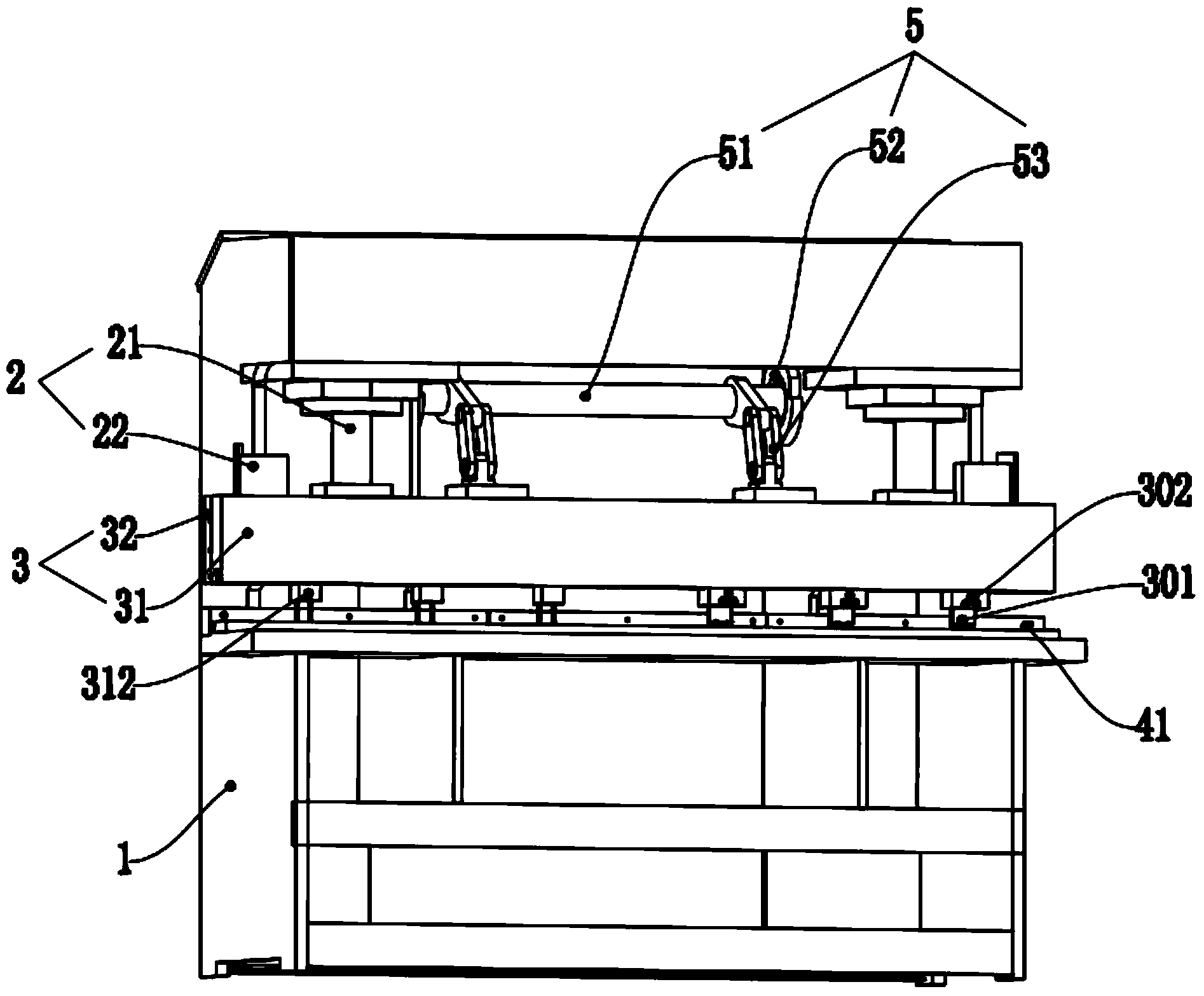
[0026] An integrated punching machine tool, comprising a frame 1, a power mechanism 2, a punching mechanism 3, a limit mechanism 4 and a rigid synchronization mechanism 5;

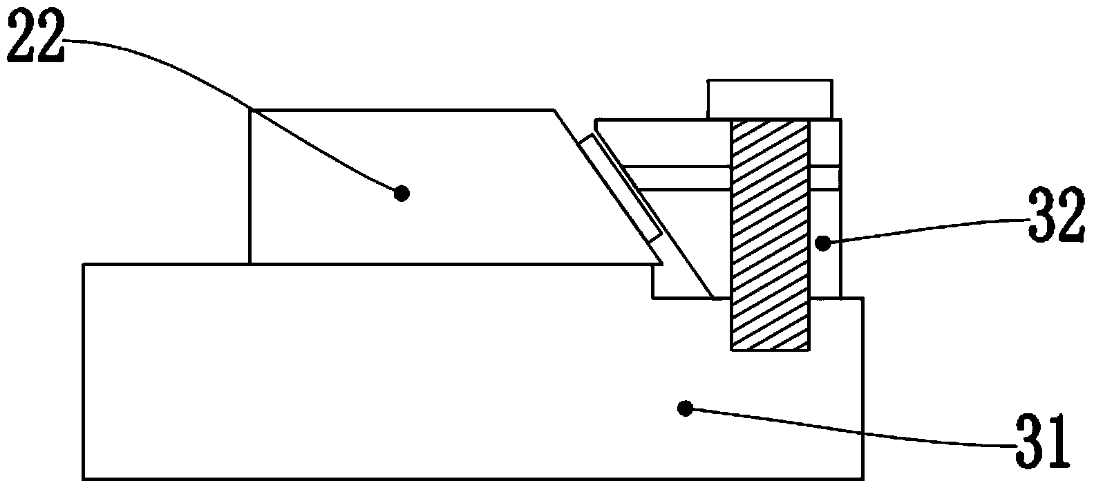
[0027] The power mechanism 2 includes a hydraulic cylinder 21 for moving up and down, and the hydraulic cylinder 21 is arranged above the frame 1;

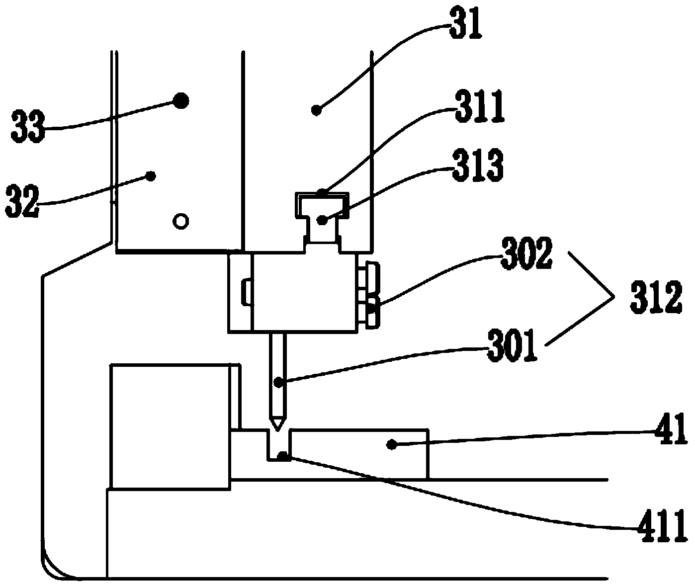
[0028] The punching mechanism 3 includes an upper die cutter plate 31 provided with a plurality of cutters 312, the two ends of the upper die cutter plate 31 are respectively connected to the movable rod of the hydraulic cylinder 21 and driven up and down by the hydraulic cylinder 21. The movement realizes punching, and the number and interval of the knives 312 of the upper die cutter plate 31 are set according to the number and interval of punching required by the workpiece;

[00...


PUM


Abstract

The invention discloses a punching integral machine tool. The punching integral machine tool comprises a frame, a power mechanism, punching mechanisms, a limiting mechanism and a rigid synchronizing mechanism, wherein the power mechanism comprises hydraulic oil cylinders which move upwards and downwards; the hydraulic oil cylinders are arranged above the frame; the punching mechanism comprises an upper die tool plate which is provided with a plurality of tools; the two ends of the upper die tool plate are connected to a movable rod of the hydraulic oil cylinder, and are driven to move upwards and downwards by the hydraulic oil cylinder to realize punching; the rigid synchronizing mechanism comprises a balance lever, a ball bearing and a connecting arm; the balance lever is rotationally and fixedly arranged on the frame through the ball bearing; the balance lever is rigidly connected to both sides of the upper die tool plate through the connecting arm. The punching integral machine tool has the advantages of completion of machining through one-time punching, high efficiency and uniform punching quality.

Description

technical field [0001] The invention relates to the technical field of mechanical processing, in particular to an integrated punching machine tool. Background technique [0002] At present, some buildings, bridges, installations, furniture, etc. use steel frame pipe structures, especially suitable for the field of row frame manufacturing. It is necessary to set connection holes for connecting pipes or screws, rivets, such as "row frame bed frames, etc." to improve production efficiency. More than 10 times. Generally, a pipe has 26 round holes or 13 square holes. Using the existing technology, it needs to be punched 26 times or 13 times. Due to the diversity of the pipe system, it is usually necessary to adjust the hole spacing of the punched holes on the pipe. Most of the existing punching machine equipment only has a single hole cutter, and only one hole can be punched at a time, and the distance between the holes is measured by the worker or the pipe is moved to adjust the...

Claims


Application Information

Patent Timeline
IPC IPC(8): B21D28/28
Inventor 李有强
Owner 李有强
Features
  • R&D
  • Intellectual Property
  • Life Sciences
  • Materials
  • Tech Scout
  • Unparalleled Data Quality
  • Higher Quality Content
  • 60% Fewer Hallucinations
Learn More